
Owner's manual

www.climacoolcorp.com
6
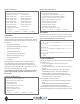
Figure 9: Service Menu (FN+7)
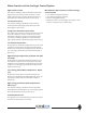
Alarm Menu
Up to 100 of the most recent occurrences stored with date
and time. Access to this log is available through the keypad.
Figure 10: Alarm Menu (FN+3 resets the alarm)
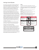
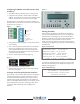
LOCAL/OFF/REMOTE
A factory provided front panel mounted 3-position selector
switch allows for:
• Local unit operation with the switch in the
“LOCAL” position
• Local emergency stop with the switch in the “OFF”
position
• Remote run/stop unit operation with the switch in
the “REMOTE” position. This requires additional
isolated contact closure inputs to request a run
command (eld-provided and installed); opening this
contact represents a stop request.
Recommended for bank shutdown:
1. Tun o the switch on the front of the Master Control
Panel
2. Remove the command for “Remote Chiller Enable”
using the BAS System or hard wire connection.
If this procedure is not followed for scheduled shutdowns,
you may risk losing the software program and/or set points.
Figure 7: Status Menu
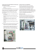
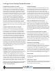
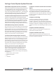
Setup Menu
Chiller system operation is determined by the values
assigned to the system variables, as predominantly found in
the Setup menu (Figure 8). The Setup menu lists a series of
sub-menus:
• General System Settings
• Heating and Cooling Set Point Menus
• Evaporator Pump Setup
• Condenser Pump Setup
• Lead Compressor Rotation Setup
• Alarm Lockout Reset (or FN+3)
• Chiller Loading Status
• Schedules
These variables are initially assigned a default value. For
most applications, these values will provide optimum
results. Once these values have been set, they are put in
permanent memory and will remain, even when all power is
removed from the Master Control Panel.
Note: If the master battery fails, the controller can lose set
points and the software program. The battery has a 720
hour backup.
Figure 8: Setup Menu (FN+2)
coo llog ic c hi ll er stat us m enu
--> a ll mo du le co mp r unloa d stat us fn5
--> m od ul e siz e stat us / --> ch il le r ope r st
--> m od1 comp1 data / --> mo d1 c om p2 data
--> m od2 comp1 data / --> mo d2 c om p2 data
--> m od3 comp1 data / --> mo d3 c om p2 data
--> m od4 comp1 data / --> mo d4 c om p2 data
--> m od5 comp1 data / --> mo d5 c om p2 data
--> m od6 comp1 data / --> mo d6 c om p2 data
--> co mp r ru nti me s / --> co mp r cycl es
--> co mp r on/of f statu s
--> e va p statu s / --> co nd status
[--> p re v] [--> cloc kse t] [--> h om e] [--> a la rm]
coo llog ic sy ste m se tu p f n2
[--> gen er al sys te m set t in gs] fn4
[--> heat & cool s et po in t men us]
[--> eva p pu mp se tu p]
[--> con d pum p set up]
[--> lea d comp r rotati on se tu p]
[--> ala rm loc ko ut r ese t]
[--> chi ll er load in g stat us]
[--> sch ed ul es]
[--> p re v] [--> statu s] [--> h om e] [--> a la rm]
coo llog ic s erv ic e men u se tu p fn 7
[--> dia gn ost ic s ma nual m od e]
[--> all m od ul e com p r un load stat us] fn5
[--> all m od ul es se ns or ca li br at io n men u]
[--> res et al l mo du l e se ns or oo r al ar ms]
[--> res et co m p al ar ms & al m de lays]
[--> mod ul e wate r tem p lim it s]
[--> water & a ir te mp li mi ts]
[--> cal ib rate wate r tem ps]
[--> lock wate r & ai r tem ps]
[--> res et co m p ru nt im es & cycl e s]
[--> pre v] [--> se tu p] [--> h om e] [-->a la rm]
mod ul e ev en t his tory (100 m os t rece nt)
====================ac t ive a la rm s======================
non e in bu ff er.
====================ac t ive fau lts=======================
non e in bu ff er.
================r et ur ne d-to-n or ma l (rt n)==============
non e in bu ff er.
================m an ually cl ear ed (clr)=================
non e in bu ff er.
[--> p re v]