
Owner's manual

www.climacoolcorp.com
8
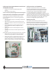
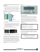
Chilled Water Flow Sensor or Switch
The Master Control Panel has an input for a dierential
pressure sensor or switch, which measures and displays
pressure drops across the chilled water main headers. If the
dierential pressure drops below a predetermined setting
for a xed period of time after the chiller receives a “RUN”
input signal, the chiller will not be allowed to run and a chilled
water ow alarm condition is displayed. The alarm condition
must be resolved, ow re-established, and a minimum
pressure dierential acknowledged by the dierential
pressure sensor or switch. The alarm clears automatically
(the alarm condition is logged for retention in the most
recent 100 alarms) which constitutes an “OK to RUN” status.
Alternatively, the Master Control Panel can be congured
to accept a contact closure from a proof-of-ow device or
dierential pressure sensor or switch indicating proper chilled
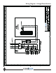
water ow (refer to the Master Control Panel wiring diagram,
page 19).
Condenser Water Flow Sensor or Switch
The Master Control Panel has an input for a dierential
pressure sensor or switch, which measures and displays
pressure drops across the condenser water main headers.
If the dierential pressure drops below a predetermined
setting for a xed period of time after the chiller receives a
“RUN” input signal, the chiller will not be allowed to run and
a condenser water ow alarm condition is displayed. This
alarm condition must be resolved and ow re-established,
and a minimum pressure dierential acknowledged by the
dierential pressure sensor or switch. The alarm clears
automatically and the alarm condition is logged for permanent
retention of the most recent 100 alarms. This will constitute an
“OK to RUN” status. Alternatively, the Master Control Panel
can congure to accept a contact closure from a proof-of-ow
device or dierential pressure sensor/switch indicating proper
condenser water ow (refer to the Master Control Panel
wiring diagram, page 19).
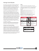
Voltage/Phase Monitor
Voltage/phase monitors are factory supplied for eld
installation with the CoolLogic Master Control Panel. The
voltage/phase monitor helps guard the chiller bank against
voltage uctuations, phase failure or phase reversal
conditions. The voltage/phase monitor has three wires
that connect to the main three phase power chiller bank
input. Two low voltage control wires are connected to the
CoolLogic Master Control Panel and must be run together
with the power wiring. Do not install control wiring in the
same conduit as line voltage wiring or with wires that switch
highly inductive loads such as contactor and relay coils.
Install one (1) monitor per bank at main power distribution
panel to monitor voltage and phasing of power to the
modules. See Wiring Diagram.
CoolLogic Control System Standard Features
Chilled Water Reset
The Master Control Panel can be programmed to reset the
leaving chilled water temperature set point based on either
return water temperature, or outdoor air temperature.
Both of these reset functions are optional and must be
activated through the appropriate setup menus. If the chiller
is operating, and it receives a chilled water reset command,
the leaving chilled water temperature setting will be allowed
to ramp toward the new setting at a rate of 2°F every seven
minutes. When the chiller is not operating and it receives
a chilled water reset command, the leaving chilled water
temperature setting will be fully reset immediately.
External Chilled Water Set Point Option
The Master Control Panel provides an input that accepts
either 2-10 VDC or 4-20 mA signals to set the leaving chilled
water set point. This input denes the set point and is not
a reset (or oset) function. This input is used with generic
Building Automation System (BAS) installations. The 2-10 VDC
and 4-20 mA ranges each correspond to a preset range from
the minimum chilled water set point to the maximum chilled
water set point.
External Condenser Water Set Point Option
Associated with heat recovery chillers, the Master Control
Panel provides an input that accepts either 2-10 VDC and
4-20 mA signals to set the leaving condenser water set point.
This input denes the set point and is not a reset (or oset)
function. This input is used with generic BAS installations. The
2-10 VDC and 4-20 mA ranges each correspond to a preset
range from the minimum condenser water set point to the
maximum condenser water set point.
Demand (or Load) Limiting
To limit the number of compressors that can be
simultaneously energized, a demand limit control is available.
The Master Control Panel provides an input channel that
accepts either 2-10 VDC and 4-20 mA signals to set the
maximum number of compressor stages allowable at any one
time. This input is typically used with generic BAS installations.
The 2-10 VDC and 4-20 mA ranges each correspond to a range
from 0% to 100% of the total available compressor stages.
Alarm Output
The relay output contact is closed whenever there is an active
latching or non-latching alarm condition present relative to a
fault parameter.
Chiller Status Output
The relay output contact is closed whenever all input signals to
the chiller are present and normal, indicating the requirement
for the chiller to operate when able.