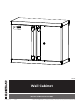
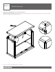
0844 Wall Cabinet INSTALLATION INSTRUCTIONS 01-18644-00 06/20 © 2020 ClosetMaid LLC | Ocala, FL 34471 | 1-800-874-0008 | www.closetmaid.
SAFETY PRECAUTIONS BEFORE BEGINNING • Please read all instructions carefully. • Familiarize yourself with all parts (see “PARTS”) and check quantities. • Follow all safety precautions (see “SAFETY PRECAUTIONS”). WARNING • CHOKING HAZARD FOR SMALL CHILDREN. This unit contains small parts which could be a choking hazard for small children. Children should be under adult supervision at all times or serious injury could occur. • ALWAYS UNLOAD UNIT PRIOR TO MOVING THE UNIT.
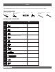
PARTS Call 1-800-874-0008 for parts and service. For faster service, have the style number ready when calling. TOOLS REQUIRED #2 and #3 Phillips Screwdrivers 7/16 in. and 1/2 in. Wrenches Level Drill 5/16 in. Masonry Drill Bit Hammer HARDWARE PROVIDED Name AA BB CC DD EE FF GG HH II JJ KK 5/16-18 x 3/4 in. Carriage Bolt 5/16-18 x 3/4 in. Flange Nut 5/16 in. Washer 1/4-20 x 1/2 in. Machine Screw 1/4-20 in. Hex Nut Electrical Bushing ST5 x 12 mm. Bolt Concrete Anchor ST4.8 x 57 mm.
PARTS Call 1-800-874-0008 for parts and service. For faster service, have the style number ready when calling.
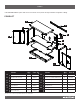
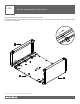
STEP 1 Attach side panels to back panel. Align both side panels (A & B) with the back panel (C) as shown. Slide the metal tabs on the back panel (C) into the matching slots on the side panels (A & B). Pull the side panels down to secure the tabs in place. A C B *Please note location of predrilled holes on each part.
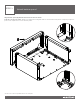
STEP 2 Attach bottom panel. Align bottom panel (D) with the bottom of the unit as shown. Push in to secure into place. Make sure that all the triangular tabs on the back and side panels completely snap into place in the square holes on the bottom panel. D *Please note location of predrilled holes on each part.
STEP 3 Attach shelves. Place the bottom shelf (F) inside the unit at the bottom. Push down to secure into place, making sure all metal tabs are connected. Please note that the bottom shelf is larger than the inner shelf and will rest on the lowest three metal tabs on the back panel. Determine where you want to position the inner shelf (G). Place inner shelf above the tabs on back panel and push down to secure, making sure all metal tabs are connected.
STEP 4 Attach brackets, spacers, and electrical bushing. Align the exterior brackets (H) and interior brackets (I) with the upper square holes on the back panel. Use a 1/2 in. wrench to secure the brackets through the holes using two 5/16-18 x 3/4 in. carriage bolts (AA), two 5/16-18 x 3/4 in. flange nuts (BB), and two 5/16 in. washers (CC) per side as shown. Please make sure the curved edge of the exterior bracket is on top when attached.
STEP 5 Attach top panel. Align top panel (E) with the top of the unit as shown. Push in to secure into place. Make sure that all the triangular tabs on the back and side panels completely snap into place in the square holes on the top panel. E *Please note location of predrilled holes on each part.
STEP 6 Secure top and bottom panels. Use a #2 Phillips screwdriver to secure the top and bottom panels to the unit using eight ST5 x 12 mm. bolts (GG) on the front corners of the unit and two bolts on the back corners. GG x 10 #2 Phillips GG *Please note location of predrilled holes on each part.
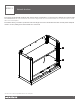
STEP 7 Attach doors. Align the right door (L) with the right side of the unit. Place the bottom lock of the door in the hole on the bottom of the door frame. Pull the top lock down, align it with the hole on the top of the door frame, and push up to lock into place. Push the bottom lock down to completely secure the door. Make sure both locks are turned inward toward the door as shown below. Please note that the right door has the slot for the key lock.
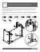
STEP 8a Attach to wall via concrete mounting. Identify which installation works best for your space. Align the unit with the location on the wall where you plan to mount it. Ensure unit is level and use a pencil to mark the top two corners of the unit on the wall and set the unit aside. Measure 2-11/16 in. down from the corner marks and make two new marks. Place the bottom of the hang track (M) on top of the two new marks.
STEP 8b Attach to wall via stud mounting. Locate studs and align the unit with the location on the wall where you plan to mount it. Ensure unit is level, use a pencil to mark the top two corners of the unit on the wall, and set the unit aside. Measure 2-11/16 in. down from the corner marks and make two new marks. Place the bottom of the hang track (M) on top of the two new marks. Make sure hang track is level and mark the two separate hole and/or slot locations on the hang track where you will hit studs.
10845 Workbench INSTALLATION INSTRUCTIONS 01-18645-00 06/20 © 2020 ClosetMaid LLC | Ocala, FL 34471 | 1-800-874-0008 | www.closetmaid.
SAFETY PRECAUTIONS BEFORE BEGINNING • Please read all instructions carefully. • Familiarize yourself with all parts (see “PARTS”) and check quantities. • Follow all safety precautions (see “SAFETY PRECAUTIONS”). WARNING • CHOKING HAZARD FOR SMALL CHILDREN. This unit • DO NOT MOUNT OR ATTACH ANYTHING TO THE SIDES, • ALWAYS UNLOAD UNIT PRIOR TO MOVING THE UNIT. • DO NOT STACK UNITS. Stacking of units can cause an contains small parts which could be a choking hazard for small children.
PARTS Call 1-800-874-0008 for parts and service. For faster service, have the style number ready when calling. TOOLS REQUIRED Level HARDWARE PROVIDED Name Qty. Allen Wrench AA 1 M8 x 20 mm.
PARTS Call 1-800-874-0008 for parts and service. For faster service, have the style number ready when calling. PRODUCT A B C Name Qty Part # A Workbench Top 1 35880 B Workbench Legs 2 35881 C Adjustable Feet 4 20621 *Please note location of predrilled holes on each part.
STEP 1 Attach workbench legs to table top. Align one workbench leg (B) with one end of the workbench top (A) as shown. Use the allen wrench (AA) to secure the workbench leg (B) to workbench top (A) using four M8 x 20 mm. bolts (BB). Repeat steps for other leg. AA x1 x8 BB B A AA BB *Please note location of predrilled holes on each part.
STEP 2 Attach adjustable feet. Align the four adjustable feet (C) with the bottom four holes on the workbench legs (B). Screw the feet in to secure. Stand the unit up on the feet. Use a level to determine if any changes need to be made to the adjustable feet. C *Maximum height extension for adjustable feet is 1.5 in. *Please note location of predrilled holes on each part.
10843 Medium Cabinet INSTALLATION INSTRUCTIONS 01-18643-00 06/20 © 2020 ClosetMaid LLC | Ocala, FL 34471 | 1-800-874-0008 | www.closetmaid.
SAFETY PRECAUTIONS BEFORE BEGINNING • Please read all instructions carefully. • Familiarize yourself with all parts (see “PARTS”) and check quantities. • Follow all safety precautions (see “SAFETY PRECAUTIONS”). WARNING • CHOKING HAZARD FOR SMALL CHILDREN. This unit contains small parts which could be a choking hazard for small children. Children should be under adult supervision at all times or serious injury could occur. • DO NOT OVERLOAD UNIT.
PARTS Call 1-800-874-0008 for parts and service. For faster service, have the style number ready when calling. TOOLS REQUIRED #3 Phillips Screwdriver 10 mm. Wrench HARDWARE PROVIDED Name Qty. ST6.3 x 12 mm. Screw AA 28 + 2 Electrical Bushing BB 1 M6-1.0 x 12 mm.
PARTS Call 1-800-874-0008 for parts and service. For faster service, have the style number ready when calling.
STEP 1 Attach side panels to back panel. Align both side panels (A & B) with the back panel (C) as shown. Slide the metal tabs on the back panel (C) into the matching slots on the side panels (A & B). Pull the side panels down to secure the tabs in place. A C B *Please note location of predrilled holes on each part.
STEP 2 Attach top panel. Align top panel (D) with the top of the unit as shown. Push in to secure into place. Make sure that all the triangular tabs on the back and side panels completely snap into place in the square holes on the top panel. D *Please note location of predrilled holes on each part.
STEP 3 Attach bottom panel. Align bottom panel (E) with the bottom of the unit as shown. Push in to secure into place. Make sure that all the triangular tabs on the back and side panels completely snap into place in the square holes on the bottom panel. E *Please note location of predrilled holes on each part.
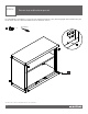
STEP 4 Attach door frame. Align the door frame (F) with the front of the unit as shown. Please note that the holes on the bottom of the door frame will match up with the upper holes on the bottom panel. Use a #3 Phillips screwdriver to secure the door frame to the unit using twelve ST6.3 x 12 mm. screws (AA). AA x 12 #3 Phillips F *Please note location of predrilled holes on each part.
STEP 5 Attach casters. Align two casters without brakes (G) with the lower holes on the bottom panel (E). Use a #3 Phillips screwdriver to secure the casters to the unit using eight ST6.3 x 12 mm. screws (AA). Align two casters with brakes (H) with the upper holes on the bottom panel (E). Use a #3 Phillips screwdriver to secure the casters to the unit using eight ST6.3 x 12 mm. screws (AA). AA x 16 #3 Phillips H G *Please note location of predrilled holes on each part.
STEP 6 Attach shelves. Stand the unit up on the casters. Place the bottom shelf (I) inside the unit at the bottom. Push down to secure into place, making sure all metal tabs are connected. Please note that the bottom shelf is larger than the inner shelf and will rest on the lowest three metal tabs on the back panel. Determine where you want to position the inner shelf (J). Place the shelf above the tabs on the inner side tracks of the unit and push down to secure, making sure all metal tabs are connected.
STEP 7 (Optional) Attach unit to workbench top. Note: This step is only if you are planning to attach a workbench top (sold separately). If not, skip to next step. Place cabinets next to each other and align workbench top with the top of the units. For each cabinet, use a 10 mm. wrench to attach four M6-1.0 x 12 mm. bolts (CC) through the top panel into the workbench top. CC x8 10 mm. *Please note location of predrilled holes on each part.
STEP 8 Attach electrical bushing. Align the electrical bushing (BB) with the large circle on the back of the unit. Push in to secure. BB x1 *Please note location of predrilled holes on each part.
STEP 9 Attach doors. Align the right door (L) with the right side of the unit. Place the bottom lock of the door in the hole on the bottom of the door frame. Pull the top lock down, align it with the hole on the top of the door frame, and push up to lock into place. Push the bottom lock down to completely secure the door. Make sure both locks are turned inward toward the door as shown below. Please note that the right door has the slot for the key lock.