Owner’s Manual Keep with machine for reference MODEL CMA-180VL Installation and Operation Manual Rev 2.00A CMA DISHMACHINES 12700 KNOTT AVENUE GARDEN GROVE, CALIFORNIA 92841 800-854-6417 FAX 714-895-2141 www.cmadishmachines.
Table of Contents Model CMA-180VL 1. SPECIFICATIONS................................................................................................. 4 1.1 2. CMA-180VL .................................................................................................................................. 4 GETTING STARTED ............................................................................................ 6 2.1. Introduction to CMA-180VL ................................................................
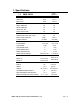
1. Specifications 1.1 Metric Equivalent CMA-180VL WATER CONSUMPTION PER RACK .89 G (3.37 L) PER HOUR 52 G (197 L) WASH TIME-SEC 49 49 RINSE TIME-SEC 12 12 VENT FAN -SEC 41 41 TOTAL CYCLE-SEC 90 90 40 40 WASH TANK CAPACITY 8 GAL. (30.3 L) PUMP CAPACITY 52 GPM (197 LPM) OPERATING CYCLE OPERATING CAPACITY RACKS PER HOUR (NSF rated) WATER REQUIREMENTS COLD WATER 41°F-65F° (5°C-18°C) HOT WATER 140F° 60°C HOT WATER INLET ½” 1.3cm COLD WATER INLET ½” 1.
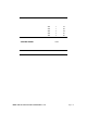
ELECTRICAL RATING SHIPPING WEIGHT MODEL CMA-180VL INSTALLATION & OPERATION Rev. 2.
2. Getting Started 2.1. Introduction to CMA-180VL 2.1.1. Plumbing Chart MODEL CMA-180VL INSTALLATION & OPERATION Rev. 2.
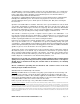
The CMA-180VL is a hot water sanitizing, single rack, door-type dishmachine. It is a stand-alone machine featuring a self-contained booster heater. The only external connections necessary are power supply, water supplies, drainpipe, and chemical dispensers. The machine utilizes recirculated wash water and fresh water final rinse. The machine is equipped with the built in Heat Recovery System which reduces significantly the humidity in the dishwashing room.
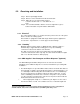
2.2. Receiving and Installation Step 1: Remove packaging material. Step 2: Remove service manual from inside the wash tank. Step 3: Adjust the feet. Set the machine in place. Level the machine side – to – side and front – to – back. Step 4: It is recommended that a distance of at least eight inches (8”) be between the table scrap sink and the dishmachine. 2.2.1. Electrical * The control panel provides a 1” conduit connection point on the rear of the panel. Refer to Section 3 for wiring options.
flexibility to permit the machine to be moved for cleaning without having to disconnect any wiring. ii. Run your dispenser wires through the conduit to the control box. iii. Run your probe wires to the control box. iv. With the machine’s power “OFF”, connect your detergent and rinse dispenser wires to the red and blue terminals of the power block supplied inside the control box. The table that follows lists the function of each conductor of the multiconductor electrical cable.
4. A 7/8” chemical probe hole is provided in the front of the wash tank heater just below hi limit switch. Insert the probe into the hole from inside the wash tank and secure it with the probe retaining nut provided. Connect ring connectors to the probe with nuts and star washers provided. 5. The final step of installing the CMA supplied Detergent and Rinse Dispenser is programming it to your specific application. The reference manual supplied with the dispenser shows you how to program it.
2.2.5. Water Tempering Kit (Optional) MODEL CMA-180VL INSTALLATION & OPERATION Rev. 2.
2.2.6. Installation Checklist Dishmachine checked for concealed damage. Hot water supply is 140° (60°C) Cold water supply is 45° (7°C) min Incoming water supply lines are ¾”. Incoming water supply is 6 gpm minimum capable at 20 psi flow pressure. Machine circuit breaker is properly sized. Service voltage and phase type are correct to machine data plate. High leg of voltage is connected to L2 (three-phase). Dishmachine is properly ventilated. Floor drain plumbing is installed with air gap.
a. After the machine has warmed up for five to ten minutes (5 – 10 min.), observe the wash and rinse temperatures. The wash temperature must be 155°F minimum. The rinse temperature must be 180°F minimum. If necessary, adjust the temperatures by removing the panel in front of the respective heater and turning the adjustment stem clockwise to increase. NOTE: Rinse water temperature must be observed during the rinse cycle. 10. Check all water and drain fittings for leaks. 11.
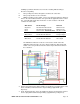
2.2.8. Electrical Requirements The CMA-180VL comes standard factory, wired for 3-phase operation. Check the electrical data plate to confirm this. Refer to “Electrical Requirements” Figure 1-A, for proper wiring instruction for both rectangular booster and wash heaters conversion. Also check the wiring diagram to properly wire the terminal power block, tank heater, and booster heater for 1 phase (or 1B diagram below).
3. Wiring Options 3-Phase and 1 Phase Wiring Options Single-Source 220V 3-Phase (20 amp/12 g*) (Without booster) Single-Source 220V 3-Phase (50 amp/8 g*) Standard Single-Source 220V 1-Phase (80 amp/4 g*) Two-Source 220V 1-Phase (50 amp/8 g*) (30 amp/10 g*) Single-Source 220V 1-Phase (30 amp/10 G*) (Without booster) *g=gauge DISPENSER HOOK-UP 1. The power signal is 208/230 volts. The power block is labeled inside the control box. Conduit holes for both detergent & rinse are supplied on the control box.
4.
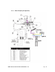
5. INITIAL PARTS KIT P/N 1100.17 P/N 00121.18 00200.10 00206.00 00302.19 00304.17 00304.19 00308.17 00308.50 00363.00 00404.85 00405.00 00411.00 00421.78 00421.90 00475.00 00501.17 00562.00 00602.00 00631.05 00706.00 00735.00 00738.15 03202.00 03202.00 03408.55 13003.17 13003.50 13304.55 13415.00 13417.47 13422.71 13417.85 13463.10 13605.00 15518.00 17523.51 DESCRIPTION CMA-180VL Drain Stopper O Ring Pump Assy 110/220V 60 Hz (Open) Pump Seal Kit CMA-180VL Buna Gasket (#302.
6. Auto-Fill Solid State Timer Pre-selected delay period can be adjusted by turning dip switches on for proper time setting. Removal of input power will reset the control. AUTO-FILL SWITCH violet violet L2 L1 WASH PUMP CONTACTOR 6 T2 WATER SOLENOID VALVE T1 1 2 3 red blue MODEL CMA-180VL INSTALLATION & OPERATION Rev. 2.
GND L3 L2 L1 DETERGENT RINSE GROUND DOOR SAFETY SWITCH { { PUMP MOTOR 1 6 2 3 WASH TANK HEATER 6kW ADJ.
GND L3 L2 L1 DETERGENT { RINSE SIGNAL { PUMP MOTOR L1 L2 L3 L1 L2 L3 L1 HEATER CONTACTOR BOOSTER HEATER CONTACTOR T1 T2 T3 T1 T2 T3 T1 T2 3 ADJ.
GND L3 L2 L1 DETERGENT RINSE GROUND DOOR SAFETY SWITCH { { 7 PUMP MOTOR L3 1 6 2 3 WASH TANK HEATER 6kW 6 ADJ.
GND L3 L2 L1 DETERGENT { PUMP MOTOR L1 L2 L3 L1 L2 L3 L1 L2 T1 T2 T3 T1 T2 T1 T2 T3 5 1 L- 2 L- TOP 3-PHASE 3 L- 8 6 BOOSTER HEATER 1 L- 2 L- TOP 1-PHASE L1 L2 TOP 3-PHASE L3 L1 L2 TOP 1-PHASE 6 kW HEATER WIRING OPTIONS ADJ.