MODELS CMA-180/180TALL Including 480V MACHINES PARTS MANUAL Rev 2.07B CMA DISHMACHINES 12700 KNOTT AVENUE GARDEN GROVE, CALIFORNIA 92841 800-854-6417 F A X 7 1 4 - 8 9 5 - 2 14 1 www.cmadishmachines.
TABLE OF CONTENTS MODEL CMA-180 1. EXPLODED VIEWS ....................................................................................... 3 1.1. Straight Frame System Assembly................................................................................................ 3 1.2. Corner Frame Assembly ............................................................................................................... 4 1.3. Drain System Assembly ..................................................................
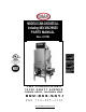
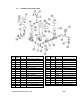
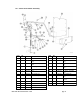
1. Exploded Views 1.1. Straight Frame System Assembly ITEM NO. 1 NO. REQ’D 1 ITEM NO. 17 NO. REQ’D 60 17532.00 Stand 00924.00 ¼” SS Washer 2 1 00535.30 3 3 17506.00 Front door Handle 18 30 00912.00 ¼”-20 Nylon Lock Nut Door 19 4 01310.00 4 6 Bullet Feet 00636.17 E Z Door Glide 20 1 17522.50 Wash Tank Heater Cover 5 6 6 17554.00 Door Guide 21 1 17522.00 Booster Heater Cover 2 17552.00 Door Stop 22 23 00914.
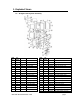
1.2. Corner Frame Assembly ITEM NO. 1 NO. REQ’D 1 NO. REQ’D 1 17532.00 Stand 17511.00 Overflow 2 1 17506.50 Door Panel Corner 3 2 17506.00 Door 15 1 17402.00 Overflow Gasket 16 24 00906.00 ¼”-20 x 1/2” Hex Head Bolt 4 4 00636.17 5 4 17554.00 E Z Door Glide 17 56 00924.00 ¼” SS Washer Door Guide 18 30 00912.00 ¼”-20 Nylon Lock Nut 6 2 7 1 17552.00 Door Stop 19 4 01310.00 Bullet Feet 17507.10 Air Gap Baffle 20 1 07522.
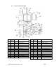
1.3. Drain System Assembly ITEM NO. 1 NO. REQ’D 1 Drain Tee Casting ITEM NO. 11 NO. REQ’D 6 00113.17 00901.00 5/16 –18x1” Hex Head Bolt 2 1 3 1 00114.00 Drain Tee Gasket 12 6 13805.00 5/16-18 Nylon Lock Nut 00121.18 Drain Stopper “O” Ring 13 1 01313.00 2” PVC Slip x MIPT Adapter *4 5 1 00121.17 Drain Stopper 14 1 05030.17 2” x 4” PVC Tubing 1 17581.00 Drain Linkage 15 1 01312.00 PVC Slip x Slip 90 Ell 6 1 17580.50 Drain Linkage Spacer 16 1 05030.
1.4. Plumbing System Assembly ITEM NO. 1 NO. REQ’D 1 00710.50 1A -- 00421.51 P/N Vacuum Breaker ¾” Watts ITEM NO. 11C NO. REQ’D -- 00786.00 Water Sol Plunger G Style Pan Head Screw SS 6-32 x 1/4” 11D -- 00707.00 Water Sol Repair Kit JE ½” DESCRIPTION P/N DESCRIPTION 1B -- 00735.60 Vacuum Breaker Brass Bonnet 12 1 13029.00 Strainer Ball Valve 3/4” 1C -- 00735.00 Vacuum Breaker Repair Kit ¾” 13 -- 13028.00 ¾” Ball Valve Repair Kit 1D -- 00739.
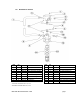
1.5. Wash Spray System ITEM NO. 1 NO. REQ’D 1 ITEM NO. 9 NO. REQ’D 8 00303.17 Manifold *2 1 00360.24 00912.00 Nylon Lock Nut ¼” – 20 Lower Spray Base Assembly 10 4 00914.10 Hex Head Bolt ¼”-20”x5/8” **3 1 4 2 00361.10 Upper Spray Base Assembly 11 2 00966.10 Hex Head SS Bolt 10-32 00304.17 Wash Spray Arm 12 4 00363.00 Spray Base Lock Pin 5 6 4 00308.50 Spray Arm End Plug SS 13 1 00302.00 Spray Base Gasket 2 00302.51 Spray Base “O” Ring 14 1 00225.
1.6. Final Rinse System ITEM NO. 1 NO. REQ’D 1 03624.00 1A -- 1B -- 1C NO. REQ’D 1 P/N DESCRIPTION ½” Vacuum Breaker Watts ITEM NO. 10 13306.17 Final Rinse Elbow Assy 03623.00 ½” Vacuum Brkr Kit- Watts 11 2 04306.00 Square Manifold Gasket 03624.25 ½” Brass Bonnet 12 2 41030.10 ½” 90 deg Ell FxF (Rm) -- 00739.50 ¾” Vacuum Breaker Cap SS 13 1 17401.00 Final Rinse Manifold 1D -- 00421.51 6-32 x ¼” SS Pan Head Screw Phillips 14 2 13642.00 ½” Brass Plug 2 1 05004.
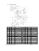
1.7 CMA-180 Door Handle Assembly ITEM NO. 1 NO. REQ’D 1 ITEM NO. 10 NO. REQ’D 2 00613.17 Door Handle 2 1 01556.50 00900.00 Cotter Pin Right Door Handle Support 1” 11 4 00906.00 ¼”-20 x ½” Hex Head screw 3 2 4 2 00603.07 Door Spring Extension Rod 12 8 00924.00 ¼” SS Washer 00602.00 Door Spring 13 8 00912.00 ¼”-20” Nylon Insert Lock Nut 5 2 17552.00 Door Stop 14 4 00610.00 Door Handle Spacer (Small) 6 2 01553.00 Door Handle Link 15 4 00611.
1.8. Corner Door Handle Assembly ITEM NO. 1 NO. REQ’D 1 ITEM NO. 13 NO. REQ’D 14 00613.04 Door Handle 2 1 00619.34 00912.00 ¼-20 Nylon Lock Nut Door Handle Mntg Plate Long 14 4 00610.00 Door Handle Spacer (Sm) 2A 1 00619.44 Door Handle Mntg Plate Short 15 4 00611.00 Door Handle Spacer (Lg) 3 1 00603.04 Door Spring Extension 16 2 00903.00 ¼-20 x 1 ¾” Hex Head Bolt 4 2 00602.00 Door Spring 17 9 00926.00 5/16” SS Washer 5 2 17506.00 Door 18 2 00910.
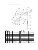
1.9. Pump System Assembly ITEM NO. 1 NO. REQ’D 1 P/N DESCRIPTION 00201.00 Pump Motor 1 HP115/230V 00201.85 Pump Motor 1 HP230/460V ITEM NO. 8 NO. REQ’D 1 00208.40 Slip Joint Nut Gasket P/N DESCRIPTION 2 1 03224.00 Small Pump Base 9 1 04204.00 Compression Nut (2.5) 3 6 00921.00 3/8”-16 x 34” Hex Head Bolt 10 2 00906.00 ¼-20 x 1/2” Hex Bolt 3A 2 00975.00 3/8-16 x 1 ½” Stud 11 2 00924.00 ¼” SS Washer 4 1 00206.30 Pump Seal Kit 12 2 00912.
1.10. Old Wash Tank Heater (Square Flange) ITEM NO. 1 NO. REQ’D 1 13417.65 Wash Tank Heater 5KW 3PH P/N DESCRIPTION 1 13417.64 Wash Tank Heater 7KW 3PH 1A 1 13417.89 Heater Thermostat 2 1 13463.10 Liquid Level Switch 3 1 13463.50 Liquid Level Switch Shield 4 1 17523.51 Hi-Limit Switch - Wash 250 Degrees 5 1 13477.20 7/8” Probe Hole Plug 6 1 13417.45 Wash Tank Heater Gasket Model CMA-180 Parts Manual Rev. 2.
1.11. Old Booster Heater (Square Flange) ITEM NO. 1 NO. REQ’D 1 17550.00 Booster Tank 2 6 13805.00 Nylon Lock Nut 5/6”-18 P/N DESCRIPTION 3 6 00926.00 Washer SS 5/16” **4 1 13417.67 Immersion Heater 12KW 3PH 4A 1 13417.89 Thermostat 12KW Heater 5 1 17523.51 Hi-Limit Switch-Booster 250 degrees *6 1 17520.00 Booster Heater Shield* 7 1 13417.47 Booster Heater Gasket 8 1 17560.00 Complete Assembly *For Straight Through Applications Only. **Includes Gasket #13417.
1.12 New Wash Tank Heater (Triangular Flange) ITEM NO. 1 NO. REQ’D 1 P/N DESCRIPTION 15518.00 Heater 6kW 220V Triangular Flange 13422.76 Heater 6kW 480V Triangular Flange 1A 1 13417.92 Heater Thermostat 2 1 13463.14 Liquid Level Switch 3 1 13463.51 Liquid Level Switch Shield 4 1 17523.51 Hi-Limit Switch - Wash 250 Degrees 5 1 13477.20 7/8” Probe Hole Plug 6 1 15518.10 Gasket for Triangular Flange Heater Model CMA-180 Parts Manual Rev. 2.
1.13. New Booster Heater (Triangular Flange) ITEM NO. 1 NO. REQ’D 1 17550.20 Booster Tank 2 3 13805.00 Nylon Lock Nut 5/6”-18 3 3 00926.00 Washer SS 5/16” 4 1 13422.71 240V 12KW Triangular Immersion Htr 13422.75 480V 12 kW Triangular Immersion Htr 4A 1 13417.92 Thermostat 12KW Heater P/N DESCRIPTION 5 1 17523.51 Hi-Limit Switch-Booster 250 degrees *6 1 17520.00 Booster Heater Shield* 7 1 8 1 Model CMA-180 Parts Manual Rev. 2.07B 15518.10 17560.
1.14. 480 Control Box Assembly p/n 18611.48 (480V machines) ITEM NO. NO. REQ’D 1 1 13905.12 Transformer Box 2 1 13423.82 Transformer 480V - 240V 3 2 13403.21 Fuse Holder - Inline 4 2 13403.40 Fuse 1.25 Amp 230V Slow Blow 5 2 13402.10 Fuse 1.50 Amp 600V Slow Blow 6 1 13420.10 Fuse Clip 2-Poll, Pressure Plate 7 1 13905.22 Transformer Box Lid 8 4 00940.50 10-32 X 3/8 Truss Head Screw P/N Model CMA-180 Parts Manual Rev. 2.
1.15. Control Box Assembly ITEM NO. NO. REQ’D P/N ITEM NO. NO. REQ’D 1 1 17503.19 P/N CMA-180 Control Box 17D 2 17400.08 30 Amp Terminal Block-Blue 2 2 3 1* 00470.10 Toggle Switch Rubber Boot 17E 2 17400.09 30 Amp Terminal Block-Natural 00409.81 Timer CMA-180 17F 1 17400.07 3A 60 Amp Terminal Block-Green 1 00501.17 Timer Motor 18 1 03408.55 Counter Face Mount 220V 4 1(2*) 00631.05 Ice Cube Relay 220V 19 4 00911.00 Pan Head Screw 8-32 x 1/2” 5 6 Ft. 00400.
1.16. Unique Parts For CMA-180TS ITEM NO. 1 NO. REQ’D 6 ITEM NO. 10 NO. REQ’D 1 00636.27 Door Guide Material 50302.06 1" MPT x 1" Barb PVC 2 3 17506.20 3 6 17554.20 Scullery Door 11 1 00303.27 Manifold Scullery Door Guide 12 1 00212.50 1-1/2”x1-1/4”Adapter 4 1 5 1 17530.20 Scullery Wrapper 13 1 00204.00 Pump Cover Large 00613.27 Door Handle S 14 1 00203.05 6 Impeller 4-1/2” 2 01553.20 Door Handle Link S 15 1 00202.00 Pump Base 7 2 00603.
1.17. Unique Parts For CMA-180TC ITEM NO. 1 NO. REQ’D 1 P/N DESCRIPTION ITEM NO. 10 NO. REQ’D 1 17506.20 Door Panel Scullery Corner 2 6 00636.27 17401.20 Final Rinse Manifold Door Guide Material 11 1 50302.06 3 2 1" MPT x 1" Barb PVC 17506.20 Scullery Door 12 1 00303.27 Manifold 4 5 4 17554.20 Scullery Door Guide 13 1 00212.50 1-1/2”x1-1/4”Adapter 1 17530.20 Scullery Wrapper 14 1 00204.00 Pump Cover Large 6 1 00563.60 Limit Switch Door Bracket 15 1 00203.
1.18. Unique Parts for CMA-180T Split Door ITEM NO. 1 NO. STR/COR 1/0 17506.23 Door Safety Brkt. Left 2 1/0 17506.24 3 1/0 13701.22 4 6/4 00636.43 5 6/4 00636.42 P/N ITEM NO. 6 NO. STR/COR 3/2 17506.42 Small Door Door Safety Brkt. Right 7 3/2 17506.34 Large Door Open Door Latch 8 1/1 17530.22 Wrapper EZ Glide Door Gide 8.5” 9 6/4 17552.22 Door Stop EZ Glide Door Gide 29.75” 10 0/1 17530.23 Corner Panel Wrap DESCRIPTION Model CMA-180 Parts Manual Rev. 2.
2. Power Switch Bulb Replacement Instructions NOTE: For Old Style Machines ONLY -- Manufactured prior to May 2002 TO REPLACE BULB 1. Using a 5mm-screw driver dismount the light module from the actuator as shown in illustration 1 & 2. 2. Replace the burnt bulb with a new one P/N 17421.10 by twisting the bulb 90 degrees. 3. Mount the light module by snapping it onto the actuator as shown in illustration 3. Model CMA-180 Parts Manual Rev. 2.
3. 180 Conversion Kit – Corner to Straight #00617.18 INSTRUCTIONS: 1. Open dishmachine doors to their highest position so that there is little spring resistance on the door handle. Remove hardware holding the door handle to the door linkage. Save all the washers and spacers. With the door handle in “UP” position, lift spring and remove from extension rod. Remove the nut attaching the eyebolt and save all hardware. 2.
4. 180 Conversion Kit – Straight to Corner #00617.17 INSTRUCTIONS: 1. Open dishmachine door to its highest position so that there is little spring resistance on the door handle. Remove hardware that holds the door handle to the door linkage. Save all the washers and spacers. Swing the door handle towards the back of the dishmachine and dismount it from the door handle support brackets. Remove the two nuts attaching the eyebolts and save the door springs. 2.