Rev.1.01A www.cmadishmachines.
Table of Contents EST-66 1. SPECIFICATIONS................................................................................................. 2 1.1. 2. EST- 66........................................................................................................................................... 2 GETTING STARTED ............................................................................................ 3 2.1. Introduction to EST -66.....................................................................
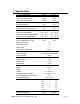
1. Specifications 1.1. EST- 66 WATER CONSUMPTION EST-66 L.T. EST-66 H.T. PER RACK (FINAL RINSE) .49 GAL. .49GAL. PER HOUR (FINAL RINSE) 119 GAL. 119 GAL. 6.75 6.
Getting Started 2. Getting Started 2.1. Introduction to EST -66 The EST is designed to give maximum cleaning in 66 inches. It represents the cleaning power of machines twice its length. The curtains incorporated in the machine minimize transfer from tank to tank during the wash and sanitizing procedures. Energy costs for running the EST-66 have been greatly reduced by the introduction of stage washing.
Getting Started 2.2. Receiving and Installation When you receive your new EST-66, complete the assembly by installing the scrap tray assembly with its overflow chute, the two wrapper shields and the curtain rods, which are shipped inside the machine. After the box has been removed from the machine, remove the left and right stainless steel wrapper shields and bolt them in place with the nuts and bolts provided. The wrapper shield with the extra curtain clamps mounts onto the dirty end of the machine.
Getting Started 2.2.1. Electrical * A 3-phase 208-240 volt AC, 60 Hz dedicated circuit should be used to supply electrical energy to the EST-44 dishwasher (see specification sheet page 2). Connect the wire that has the highest voltage (stinger lead) to the main contactor’s power terminal L2. Power lead wires (L1, L2 and L3) used for the EST-44 at installation must comply with all local and State electrical codes. 2.2.2.
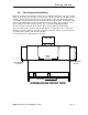
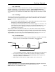
Getting Started P/N 13505.14 205 RACKS/HOUR 243 RACKS/HOUR Figure 2.2.3b 4. On a 3-phase machine the water pump motors are also 3-phase and, depending on which terminal each phase is connected to, the motor can rotate in either direction. Check the direction of rotation by removing the dust cap on the back of the motor. The motors must turn clockwise looking at the shaft from the back of each motor. To change the direction of rotation, switch any two power lead wires at the motor. 5.
Getting Started 2.2.4. Optional Table Limit Switch (Please see section 5 for Installation Instructions) MODEL EST-66 Service & Parts Manual Rev. 1 .
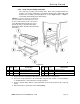
Getting Started 2.2.5. Scrap Tray Assembly Installation The scrap tray assembly and overflow chute, which came packaged inside the machine, can easily be installed by executing the following steps: Figure 2.2.5 below illustrates the assembly as it would appear for a Left-to-Right machine – a Right-toLeft machine would simply be the mirror image. Caution: 1.For proper spacing, the SS flat washer (item 5) must not be located between the head of the truss head bolt and the inside of the machine. 2.
Getting Started 2.2.6. Pump Impeller Note Figure 2.2.5 Installation: When installing the water pump impeller the Nylon Lock Nut indicated by the arrow in Figure 2.2.5 must be in place to prevent the impeller from spinning off of the shaft and damaging the motor. Removal: The Nylon Lock Nut indicated by the arrow in Figure 2.2.5 must be removed before attempting to remove the water pump impeller. MODEL EST-66 Service & Parts Manual Rev. 1 .
Getting Started 2.2.7. Optional Hood Adapter (Set of Two) An optional Hood Adapter set (P/N 13901.82) is available. proper installation are given below. The dimensions for Caution: open the damper just slightly to prevent heat loss . Warning: CMA vent hood adapters have been engineered to retain the temperature within the dishmachine. CMA's vent hood adapters are designed to draw steam beyond the outside end curtains.
Getting Started 2.2.8. Field Installed Accessories Qualified personnel must perform installation of the accessory chemical pumps. 2.2.8.1. Chemical Dispensers 1. Check valves should be installed directly at the mixing chamber coupling. There are two 1/8” FPT mounting holes provided, which will position the check valves parallel to the machine avoiding any chemicals from dripping onto the stainless steel should a leak develop.
Getting Started MODEL EST-66 Service & Parts Manual Rev. 1 .
Getting Started 2.3. Safety Tips for the EST-66 DANGER: Always turn off the circuit breaker at the wall when working on this dishmachine. Even with the machine’s power switch off there is a live connection coming to the switch, so turn off the circuit breaker as well. CAUTION: Do not get in the path of the conveyor rocker arm or the conveyor’s moving bar. Do not reach into the rocker arm area without first making sure the dishmachine is turned off at the circuit breaker.
Operation 3. Operation 3.1. Initial Setup 3.1.1. Rinse Pressure Regulator The CMA-44 requires a supply water pressure of 24 PSI minimum. The supply water regulator then reduces the pressure. Use the following procedure to adjust the rinse pressure to 20 PSI: 1. Close the door on the machine. 2. Turn the Power switch to the "ON" position. 3. Using a rod or something long to avoid contact with the rinse water, actuate the final rinse trip switch—this activates the water solenoid.
Operation 3.2. Beginning Operation To run the dishmachine, perform the following steps: 1. Close both drains (valve handles in vertical position). CLOSE CLOSE 2. Turn on the power to the dishmachine. The machine will automatically fill itself. The float when sensing adequate water level energizes an ice cube relay, which will allow power to go to the heaters while the door is closed and the water temperature is below the thermostat setting. 3.
Operation 5. At the end of the shift and after heavy periods of accumulation, clean the three strainer trays inside the machine. STRAINER TRAY Also, at the end of each shift, remove and clean the six spray arms. Then reinstall them into the machine. SPRAY ARM Also, when water becomes heavily soiled, drain the tanks and refill the machine. 6. Check chemical buckets. Make sure there is an adequate supply of detergent, rinse aid and (EST-66 only) sanitizer.
Operation 3.2.1.1. Low Temperature Applications See dispenser manufacturing operational adjustments for Low Temp applications. instructions for sanitizer The sanitizing pump operates when the fresh water enters the machine during final rinse. The water is treated at 50 PPM (parts per million). The pressure regulator is adjusted to 20-PSI. This allows 0.49 gallons of water to enter the machine each time a rack is washed.
Operation out). Check that the float switch is working properly (this will also cause the heater contactor to pull in and drop out when actuated). 6. Replace all the strainer trays into their proper position and fill the machine. 7. Place a rack into the machine and observe the spray pattern of the pre-wash, the wash, and the final rinse. a. Check the titration of the wash tank at this point. b. While the rack is in the final rinse, check for 50PPM residual chlorine in the final rinse. c.
Operation 3.4.
Operation 4. EST-66 Customer Notice MODEL EST-66 Installation and Operation Manual Rev. 1 .
Operation TIPS TO SAVE A SERVICE CHARGE If the Lessee of this equipment initiates a service call and it is subsequently determined that the problem does not relate to part failure or out of chemicals, there will be a minimum service charge for a service person to respond. It is recommended that you check the following items before initiating a service call: Circuit breaker position. Should be “ON”. Clogged drains (at any point in drain line). Lack of soft water (check salt level in brine tank).
Operation 5. Electrical Diagram For 230V EST-66 MODEL EST-66 Installation and Operation Manual Rev. 1 .
ROCKER SWITCH MODEL EST-66 Installation and Operation Manual Rev. 1 .01A BOOSTER HEATER CONTACTOR T1 L1 L2 TOP 3-PHASE L3 L- 1 L2 TOP 1-PHASE 12kW HEATER WIRING OPTIONS L1 T2 T3 L1 2 L2 3 L2 L3 Use two 10 kW heating elements for 70°F rise. Use one 12 kW heating element for 40°F rise. 24 KW BOOSTER HEATER ADJ. THERMOSTAT HI LIMIT SWITCH WIRE DIAGRAM FOR E-TEMP HEATER Operation 6.
Operation 7. Electrical Diagram For 480V EST-66 MODEL EST-66 Installation and Operation Manual Rev. 1 .