
Specifications


Getting Started
2.2.1. Electrical
*
A 3-phase 208-240 volt AC, 60 Hz dedicated circuit should be used to supply electrical energy to
the EST-44 dishwasher (see specification sheet page 2). Connect the wire that has the
highest voltage (stinger lead) to the main contactor’s power terminal L2. Power lead wires
(L1, L2 and L3) used for the EST-44 at installation must comply with all local and State electrical
codes.
2.2.2. Plumbing*
The water supply connection is made with a ½” hot water line to the water supply inlet on the top
of the machine. The water supplied to the machine must be a minimum of 140° F for the EST-
66L and a minimum of 180° F for the EST-66H.
NOTES:
1. The Low Temp machine (EST-66L) can be supplied with single point water inlet kit with
braided hose included for fill and final rinse inlets connection.
1. The High Temp machine (EST-66H) comes with two water supply line connections. One
for the final rinse at 180° F and the second line is to fill the wash tank with 140° F —the
water will be heated to the appropriate temperature by the wash tank heater. (See
specification sheet on page 2).
There are two 2” drain connections to be made. One connection is made at either end of the
horizontal drainpipe coming from the wash tank and the other connection is made at the scrap
tray drain. (Instructions for installing the scrap tray assembly are provided in section
2.2.5 Scrap
Tray Assembly
.) One of the ends of the horizontal drainpipe has a cap on it – simply move the
cap to the other end if it’s currently on the end needed for the drain connection.
2.2.3. Installation Notes
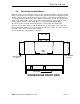
1. Tables must slant into the machine for proper drainage (for each 28" of table length
a drop of at least ¾” in table height is recommended). See
Figure 2.2.3a.
T
A
B
L
E
S
L
A
N
T
FRESH WATER
TO SCRAP
ACCUMULATOR
WASH
PRE-RINSE/RINSE
DISH FLOW
Figure 2.2.3a
See also installation instructions on EST-44 conveyor (Section 4. Customer Notice)
2. The scrap tray assembly is placed inside the machine for shipping. Follow the
instructions provided in section
2.2.5 Scrap Tray Assembly to properly attach the
scrap tray assembly to the dishmachine.
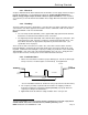
3.
Figure 2.2.3b shows the different settings available on the conveyor cam.
*
Electrical and plumbing connections must be made by a qualified person who will comply with all
available Federal, State, and Local Health, Electrical, Plumbing and Safety codes
MODEL EST-66 Service & Parts Manual Rev. 1 .01A Page
5