
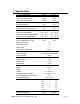
Specifications


Getting Started
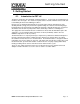
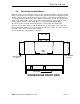
2.2.5. Scrap Tray Assembly Installation
The scrap tray assembly and overflow chute, which came packaged inside the
machine, can easily be installed by executing the following steps:
Figure 2.2.5 below
illustrates the assembly as it would appear for a Left-to-Right machine – a Right-to-
Left machine would simply be the mirror image.
Fi
Figure 2.2.4
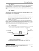
Caution:
1.For proper spacing, the SS flat washer
(item 5) must not be located between the head of
the truss head bolt and the inside of the machine.
2.
The Illustration below shows the correct
placements of the scrap trap holder. Don’t
install upside down, otherwise water deflection
takes
p
lace.
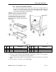
ITEM
NO.
NO.
REQ’D
P/N DESCRIPTION
ITEM
NO.
NO.
REQ’D
P/N DESCRIPTION
1 1 01577.20 Scrap Trap Drawer Molded 4 11 00912.00 ¼-20 Nylon Lock Nut
2 1 01577.10 Scrap Trap Body Molded 5 11 00924.00 ¼” SS Flat Washer
3 1 17579.00 Scrap Trap Holder
6 4 00906.00 ¼-20 X ½” Hex Head Bolt
1. Remove the items from their packing and verify that all the pieces are present.
2. Secure the scrap trap holder to the dishmachine using the four ¼-20 X ½” Hex Head Bolts,
¼” SS Flat Washers, and ¼-20 Nylon Lock Nuts provided.
3. Set the scrap trap body—with the scrap trap drawer inserted—into position on the scrap trap
holder.
4. Attach the drain as specified in section
2.2.2 Plumbing.
MODEL EST-66 Service & Parts Manual Rev. 1 .01A Page
8