
Specifications
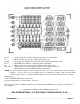
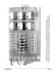
CONSTRUCTION & INSTALLATION
EXPANDER 240 ELECTRONIC CRYSTAL SWITCH
INTRODUCTION
The EXPANDER 240 is a compact crystal switch which allows up to six synthesizer mixing crystals to be remotely
selected. Its purpose is to provide new injection signals for loop mixing in PLL synthesizer circuits, or additional
mixing frequencies for older 23-channel type CBs using crystal synthesizers. Each crystal position includes a
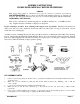
series trimmer capacitor for exact frequency adjustment if needed. The appropriate mixing crystal is removed
from the radio, and installed in the EXPANDER 240 PC board instead. Two wires from the EXPANDER 240 are
installed in the empty crystal hole in place of the removed crystal. Crystal selection is made electronically
through diodes. This eliminates the problem of stray wire capacitance often occurring in mechanical switching
devices. Because of this advantage, the crystal PC board can be placed physically close to the required circuit,
while the switching wires can be made long enough to reach the actual switch mounted elsewhere on the chassis.
(Often a relatively long distance from the PC board.)
Generally speaking, any PLL type radio using a loop mixing frequency can be expanded by 40 channels per mixing
crystal (or 23 channels per crystal, in some early PLL circuits), up to the limit of the CB’s tuning circuits. Thus a
typical American 40-channel CB can be made to work on 80, 120, or even 160 total consecutive channels in some
cases. For the older 23-channel crystal-synthesized radios, the extra coverage will be 20 channels, for a total of
43 consecutive channels.
CIRCUIT DESCRIPTION
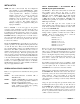
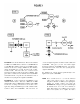
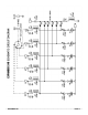
The electrical operation is very simple. Refer to the Schematic Diagram, Page 9. Wires from holes “A” and “B”
are connected in place of the crystal that was removed from the radio. A regulated DC voltage of +7-10 VDC
from the radio is applied through the user’s switch. The associated diode (D1-D6) will find a path to ground via
R1 and L7 and conduct. R1 and L7 are common to all switching diodes and are used for RF isolation. In addition
each diode is further decoupled by C1-C6 and L1-L6. When the diode conducts, there will be RF continuity from
hole “B” through C7, the associated diode, the series capacitor CT1-CT6, the crystal, and finally to hole “A.”
NOTE: Either a series capacitor or a bare jumper wire must be installed in the holes marked
“CT1-CT6.” Otherwise there would be no RF continuity to ground, and the circuit
wouldn’t oscillate. Since the trimmer capacitors are the most expensive parts in this kit,
and since few American CBs can cover more than 120 channels anyway, only three
trimmers are provided. They often aren’t even needed, and in most cases a bare jumper
wire will work. If a crystal does need trimming, try a fixed ceramic disc capacitor of
about 10-68 pF in these holes first. (Extra trimmers are available from us at $1 each.)
Copyright 1985–2002 by L.M. Franklin. All rights reserved
Published by:
CBC INTERNATIONAL • P.O. BOX 30655 • TUCSON AZ 85751 U.S.A.
TEL/FAX: 888-I-FIX-CBs (1-888-434-9227), (520) 298-7980
Internet: www.cbcintl.com • Email: info@cbcintl.com