
Service manual

Larger wires and tight connections will provide longer service life for components. For high current wires it
is highly recommended that terminal blocks or soldered connections be used with shrink tubing to protect
the connections. Do not use insulation displacement connectors (e.g. 3M
®
Scotchlock type connectors).
Route wiring using grommets and sealant when passing through compartment walls. Minimize the number
of splices to reduce voltage drop. High ambient temperatures (e.g. underhood) will signicantly reduce the
current carrying capacity of wires, fuses, and circuit breakers. Use "SXL" type wire in engine compartment.
All wiring should conform to the minimum wire size and other recommendations of the manufacturer and
be protected from moving parts and hot surfaces. Looms, grommets, cable ties, and similar installation
hardware should be used to anchor and protect all wiring. Fuses or circuit breakers should be located
as close to the power takeoff points as possible and properly sized to protect the wiring and devices.
Particular attention should be paid to the location and method of making electrical connections and splices
to protect these points from corrosion and loss of conductivity. Ground terminations should only be made
to substantial chassis components, preferably directly to the vehicle battery. The user should install a
fuse sized to approximately 125% of the maximum Amp capacity in the supply line to protect against
short circuits. For example, a 30 Amp fuse should carry a maximum of 24 Amps. DO NOT USE 1/4"
DIAMETER GLASS FUSES AS THEY ARE NOT SUITABLE FOR CONTINUOUS DUTY IN SIZES ABOVE
15 AMPS. Circuit breakers are very sensitive to high temperatures and will "false trip" when mounted in hot
environments or operated close to their capacity.
WARNING!
Wiring Instructions
5
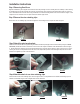
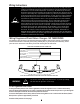
Wiring Diagram and Flash Pattern Changes - NO TAKEDOWNS
It is advisable to leave an extra loop of cable when installing the lightbar to allow for future changes or reinstallations.
Connect the black lead to a solid frame ground (earth), preferably the (-) or ground (earth) side of the battery, and the
power wire to the +12V terminal of the battery. Connect the remaining wires as shown below.
NOTE: FOR SUPERVISORS WITH TAKE DOWN OPTION SEE DIAGRAM ON NEXT PAGE
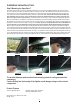
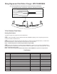
FUSE WITH CUSTOMER SUPPLIED 10 AMP FUSE
GREEN (PATTERN SELECT)
WHITE (DIMMING)
RED (POWER)
YELLOW (LEVEL 3)
ORANGE (LEVEL 2)
BLUE (LEVEL 1)
BLACK (GND)
This Product contains high intensity TriCore devices. To prevent eye damage,
DO NOT stare into light beam at close range.
WARNING!
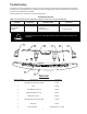
TriCore Lighthead Flash Pattern
To change the ash patterns of the TriCore Lightheads, activate the Lightbar in Level 1 and then momentarily
touch the Green (Pattern Select) wire to +power. Repeating this procedure allows the operator to cycle through the
numerous ash patterns offered until the desired pattern is achieved.
To reset the ash patterns to the factory default, activate the Lightbar in Level 1 and then hold the Green (Pattern
Select) wire to +power for approximately 4 seconds.
For table of ash patterns see next page.