
Energy Guide
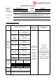


Project No.
Tested By
Applicant
Elec-Tech International Co., Ltd.
Test Date
Model No.
Rated Life
Standard/Method
Test Laboratory
Remarks
Jackson Zeng
2/2/2015
ENERGY STAR® Program Requirements Product Specification
for Luminaires (Light Fixtures) Eligibility Criteria Version 1.2
542831XX (where “xx” denotes color temperature, 01~10 identifies 2700K, 11~30identifies 3000K,
31~40 identifies 3500K, 41~50 identifies 4000K)
542831XX
4786795152-08
50000 h
DATA SHEET (Luminaires)
UL Verification Services (Guangzhou) Co., Ltd.
ADD: Building A1, 1F & 2F, Nansha Science and Technology Innovation Center, No. 25, South
Huanshi Avenue , Nansha District, Guangzhou 511458, China
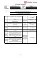
Maximum led source operating temperature measurements were taken on one test sample per model with a
thermocouple and YOKOGAWA temperature meter. The SSL sample was allowed to reach thermal
equilibrium for at least 3 hours before measurements were taken. Led source temperature was measured at
the point as indicated by the included diagram in accordance with manufacturers declared hot spot location.
The maximum temperature was recorded for the sample. A simulated ceiling or other enclosure may be
used in accordance to UL 1598 as applicable.
In-Situ Temperature Measurement Test (ISTMT)
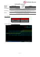
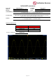
Each test sample was operated at rated input voltage. Light output waveform shall be measured with a
photodetector, transimpedance amplifier and oscilloscope. The AC ripple on the output DC line was
measured and recorded by the oscilloscope according to Energy Star directions.
Each test sample was operated in its designated orientation at rated input voltage in a 25 ± 5º C ambient . A
photodetector is used to monitor the luminaire light output. Time was recorded when the sample was fully
illuminated and reached 90% of stabilized lumen output.
Maximum driver case temperature measurement was taken on one test sample per model with a
thermocouple and YOKOGAWA temperature meter. The SSL sample was allowed to reach thermal
equilibrium for at least 3 hours before measurements were taken. Driver case temperature was measured
at the point as indicated by the included diagram in accordance with manufacturers declared hot spot
location. The maximum temperature was recorded for the sample. A simulated ceiling or other enclosure
may be used in accordance to UL 1598 as applicable.
Operating Frequency
Maximum Measured Ballast or Driver Case Temperature
Source Start Time & Run-Up Time
Page 5 of 12