
Installation Guide

5 HOMEDEPOT.COM
Please contact 1-877-527-0313 for further assistance.
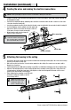
Knock out holes
Metal tabs
4
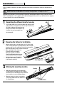
Feeding the wires and making the electrical connections
NOTE: Put the gasket (BB) on any knock out hole on the fixture to better protect the wires.
□ Feed the electrical connection wires through any knock out hole, through the gasket (BB), and then through the
mounting bracket (AA).
□ Insert the hot and neutral (black and white) wires from the electrical box into the wire connectors of the same
color wires from the housing (A).
□ Insert the ground wire from the electrical box into the wire connector attached to the green wire from the housing (A).
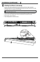
□ If a 0-10v dimming circuit is available, insert the purple and
pink wires from the electrical box into the wire connectors
of the same color wires from the housing (A).
□ Wrap the wires with electrical tape for
a more secure connection.
NOTE: Tuck all electrical
connections into the electrical box.
The connection wires can be held in
place by the metal tabs, if needed.
BB
AA
A
A
Installation (continued)
5
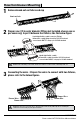
Attaching the housing to the ceiling
□ Position the wires back inside the electrical box. Mount the mounting bracket (AA) to the electrical box using
the two electrical box screws (CC).
□ Drill a 1/8-in. pilot hole into the screw locations marked on the ceiling. You can also use an awl or nail to
dimple the screw holes.
□ Install a drywall anchor (DD) and a mounting screw (EE) in each drilled mounting hole, but do not tighten fully.
□ Align the 2 mounting keyholes on the housing (A) with the 2 mounting screws (EE) in the ceiling. Once the
screw heads are through the large ends of the keyholes, slide the housing until the heads of the screws
slide into the narrow ends of the keyholes.
□ Finish tightening the mounting screws (EE) until
the fixture housing (A) is tightly secured to
the mounting surface.
NOTE: The drywall anchors
(DD) are only to be used for
mounting the fixture onto
plaster or drywall surfaces.
Wire connectors
CC
DD
EE
AA