
Installation Guide


8
Installation (continued)
5
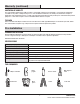
Making the electrical connections
inside the xture
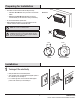
□ Loosen the two mounting base screws (C) using a Phillips
screwdriver to open the xture. (Fig. 1)
□ The xture will open sideways and stay connected on the
hinge.(Fig. 2)
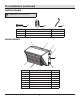
□ Irrespective of the type of mount (Junction box or Surface
Conduit) make wiring connections inside the xture as per
the instructions given below.
NOTE: The mounting plate screws (C) come pre-installed on
the light xture.
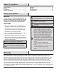
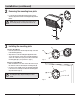
ON/OFF Wiring (Non Dimming) Method:
□ If necessary, strip 3/8 in. of insulation from junction box or
xture (A) wires.
□ Connect the xture black wire to the supply black wire ((+)
line), and xture white wire to the supply white wire ((-)
common) by twisting the exposed wires together and using
the wire nuts (BB). Ensure there are no loose wires.
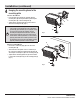
□ Connect the supply ground wire to the green xture ground
wire by twisting the exposed wires together and using the
wire nuts (BB).
NOTE: Hold stripped ends near each other and align any
frayed strands (do not twist wires).
Push the wires into wire nut (BB) and use your ngers to
twist the wire nut clockwise until tight. Check for tightness by
pulling wires.
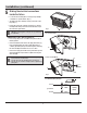
(+) Line
Black
White
Lighting
Fixture
Green
(-) Common
Ground
3/8 in.
Non-Dimming Wiring Diagram
C
D
Junction Box Mount
Surface Conduit Mount
BB
Fig. 2
Fig. 1
BB
D
A
A