
Installation Manual


INS_FVT/FVR812_REV–
05/27/10
PAGE 3
TECH SUPPORT: 1.888.678.9427
INSTALLATION AND OPERATION MANUAL FVT/FVR812
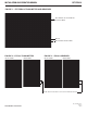
FIGURE 4 – DATA SWITCH POSITIONS
The mode for each data channel is configured using a pair switches on the front panel of the unit.
Switch
4) RS485 4-Wire
1 2
1 2
1 2
1 2
1) RS232 2) RS422, Bi-Phase or
Manchester
3) RS485 2-Wire,
Sensornet
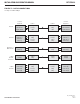
1) RS232
DIN (–)
DOUT (–)
GND
2) RS422,
Bi-Phase,
Manchester
DIN (+)
DIN (–)
DOUT (+)
DOUT (–)
GND
3) RS485 2-Wire,
Sensornet
DIN (+)
DIN (–)
GND
4) RS485 4-Wire
DIN (+)
DIN (–)
DOUT (+)
DOUT (–)
GND
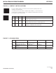
Termination Note
A 120 ohm termination resistor is applied to the differential inputs when
TERM is wired directly to DIN – (see diagram below).