
Installation Manual


INS_FVT/FVR812_REV–
05/27/10
PAGE 5
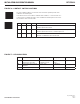
FIGURE 7 – LED INDICATORS
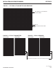
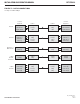
FIGURE 6 – CONTACT SWITCH POSITIONS
TECH SUPPORT: 1.888.678.9427
INSTALLATION AND OPERATION MANUAL FVT/FVR812
LINK VIDEO (1 – 8) DATA (1 – 2) POWER
GREEN
Communication link has been
established over optical fiber
Active video signal present
on the BNC connector.
Active data signal
present
Unit powered up
RED
Communication link has not been
established
No video signal No data signal –
OFF
Not powered up correctly – – Unit powered down
The four CONTACT switches on the front of the unit set the operating mode of the
CONTACT OUT terminal pair.
It can either function as an alarm to indicate fault conditions, or it can function as a
contact closure to indicate the state of the CONTACT IN terminal pair on the rear of
the unit at the other end of the fiber.
1234
ON OFF OFF OFF Closed when optical Port has established link.
Open when Optical Port has lost link.
ON ON ON OFF Closed when Optical Port has established link and all video signals are present.
Open when Optical Port has lost Link, or if a Video signal is lost.
ON ON ON ON Contact Closure mode.
State based on CONTACT IN at other end of fiber link.