268135-002.book Page 1 Thursday, October 24, 2002 4:10 PM b Maintenance and Service Guide Compaq Evo Notebook N800c Series Compaq Evo Notebook N800v Series Compaq Evo Notebook N800w Series Compaq Presario 2800 Mobile PC Document Part Number: 268135-002 October 2002 This guide is a troubleshooting reference used for maintaining and servicing the notebook.
68135-002.book Page 2 Thursday, October 24, 2002 4:10 PM © 2002 Compaq Information Technologies Group, L.P. Compaq, the Compaq logo, Evo, and Presario are trademarks of Compaq Information Technologies Group, L.P. in the U.S. and/or other countries. Microsoft and Windows are trademarks of Microsoft Corporation in the U.S. and/or other countries. Intel, Pentium, and SpeedStep are trademarks of the Intel Corporation in the U.S. and/or other countries.
268135-002.book Page iii Thursday, October 24, 2002 4:10 PM Contents 1 Product Description 1.1 Features . . . . . . . . . . . . . . . . . . . . . . . . . . . . . . . . . . . 1–2 1.2 Clearing a Password. . . . . . . . . . . . . . . . . . . . . . . . . . 1–4 1.3 Power Management . . . . . . . . . . . . . . . . . . . . . . . . . . 1–5 1.4 Computer External Components . . . . . . . . . . . . . . . . 1–6 1.5 Design Overview . . . . . . . . . . . . . . . . . . . . . . . . . . . 1–16 2 Troubleshooting 2.
268135-002.book Page iv Thursday, October 24, 2002 4:10 PM Contents 4 Removal and Replacement Preliminaries 4.1 Tools Required . . . . . . . . . . . . . . . . . . . . . . . . . . . . . . 4.2 Service Considerations. . . . . . . . . . . . . . . . . . . . . . . . Plastic Parts . . . . . . . . . . . . . . . . . . . . . . . . . . . . . . . . Cables and Connectors . . . . . . . . . . . . . . . . . . . . . . . 4.3 Preventing Damage to Removable Drives . . . . . . . . . 4.4 Preventing Electrostatic Damage . . . .
268135-002.book Page v Thursday, October 24, 2002 4:10 PM Contents 6 Specifications A Connector Pin Assignments B Power Cord Set Requirements 3-Conductor Power Cord Set . . . . . . . . . . . . . . . . . . . . . . General Requirements . . . . . . . . . . . . . . . . . . . . . . . . Country-Specific Requirements . . . . . . . . . . . . . . . . . . . . Notes . . . . . . . . . . . . . . . . . . . . . . . . . . . . . . . . . . . . .
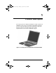
268135-002.book Page 1 Thursday, October 24, 2002 4:10 PM 1 Product Description The Compaq Presario 2800 Series Mobile PC and Evo Notebook N800 Series offer advanced modularity, Intel Mobile Pentium 4 processors with SpeedStep technology with 64-bit architecture, industry-leading Accelerated Graphics Port (AGP) implementation, and extensive multimedia support. Figure 1-1.
268135-002.book Page 2 Thursday, October 24, 2002 4:10 PM Product Description 1.1 Features 1–2 ■ 2.2-, 2.0-, 1.9-, 1.8-, 1.7-, 1.6-, 1.5-, or 1.4-GHz Intel Mobile Pentium 4 processor with SpeedStep technology, with 256-KB integrated L2 cache, varying by computer model ■ ATI Mobile Radeon 9000 or ATI P7 graphics controller with 32 to 64 MB of shared SDRAM and 4X AGP graphics card, varying by computer model ■ 128-MB high-performance Synchronous DRAM (SDRAM), expandable to 1.
268135-002.book Page 3 Thursday, October 24, 2002 4:10 PM Product Description ■ 60-, 40-, 30-, or 20-GB high-capacity hard drive, varying by computer model ■ Support for the following drives through the MultiBay: ■ ❏ 1.
268135-002.book Page 4 Thursday, October 24, 2002 4:10 PM Product Description 1.2 Clearing a Password If the notebook you are servicing has an unknown password, follow these steps to clear the password. These steps also clear CMOS: 1. Prepare the computer for disassembly (refer to Section 5.3, “Preparing the Computer for Disassembly,” for more information). 2. Remove the RTC battery (refer to Section 5.17, “Disk Cell RTC Battery”). 3. Wait approximately five minutes. 4.
268135-002.book Page 5 Thursday, October 24, 2002 4:10 PM Product Description 1.3 Power Management The computer comes with power management features that extend battery operating time and conserve power.
268135-002.book Page 6 Thursday, October 24, 2002 4:10 PM Product Description 1.4 Computer External Components The external components on the front and right side of the computer are shown in Figure 1-2 and described in Table 1-6. . Figure 1-2. Front and Right Side Components Table 1-6 Front and Right Side Components Item Component Function 1 Stereo speakers (2) Produce stereo sound. 2 Power/Suspend light On: Power is turned on. Off: Power is turned off. Blinking: Computer is in Suspend mode.
268135-002.book Page 7 Thursday, October 24, 2002 4:10 PM Product Description Table 1-6 Front and Right Side Components (Continued) Item Component Function 3 Display release latch Opens the computer. 4 Battery light On: A battery pack is charging. Blinking: A battery pack that is the only available power source has reached a low-battery condition. 5 Battery bay Accepts an 8-cell lithium ion (Li ion) battery pack. 6 Hard drive bay Supports the removable primary hard drive.
268135-002.book Page 8 Thursday, October 24, 2002 4:10 PM Product Description The computer rear panel and left side components are shown in Figure 1-3 and described in Table 1-7. Figure 1-3. Rear Panel and Left Side Components Table 1-7 Rear Panel and Left Side Components Item Component Function 1 Vent Allows airflow to cool internal components. CAUTION: To prevent damage, the computer shuts down if an overheating condition occurs. Do not block the cooling vent.
268135-002.book Page 9 Thursday, October 24, 2002 4:10 PM Product Description Table 1-7 Rear Panel and Left Side Components (Continued) Item Component Function 4 External monitor connector Connects an external monitor or overhead projector. 5 S-Video connector Connects a television, VCR, camcorder, or overhead projector. 6 USB connectors (2) Connect USB devices. 7 RJ-11 modem jack Connects the modem cable to an internal modem. A modem cable is included with internal modem models.
268135-002.book Page 10 Thursday, October 24, 2002 4:10 PM Product Description The computer keyboard components are shown in Figure 1-4 and described in Table 1-8. Figure 1-4. Keyboard Components Table 1-8 Keyboard Components Item Component Function 1 F1 through F12 Perform preset functions. function keys 2 1–10 Num lock key On: Num lock is on and the embedded numeric keypad is enabled.
268135-002.book Page 11 Thursday, October 24, 2002 4:10 PM Product Description Table 1-8 Keyboard Components (Continued) Item Component Function 3 Embedded numeric keypad Converts keys to numeric keypad. 4 Cursor control keys Move the cursor around the screen. 5 Windows application key Displays a menu when using a Microsoft application. The menu is the same one that is displayed by pressing the right mouse button. 6 Windows logo keys Displays the Windows Start menu.
268135-002.book Page 12 Thursday, October 24, 2002 4:10 PM Product Description The computer top components are shown in Figure 1-5 and described in Table 1-9. Figure 1-5. Top Components Table 1-9 Top Components Item Component Function 1 Display lid switch Turns off the computer display if the computer is closed while on. 2 Power light On: Power is turned on. Blinking: Computer is in Suspend mode.
268135-002.book Page 13 Thursday, October 24, 2002 4:10 PM Product Description Table 1-9 Top Components (Continued) Item Component Function 5 Power button Turns on the computer. Use the operating system Shut Down command to turn off the computer. 6 Digital audio button Launches Windows Media Player to play MP3 music. 7 Volume control buttons Adjust the volume of the stereo speakers. 8 Caps lock light On: Caps lock is on.
268135-002.book Page 14 Thursday, October 24, 2002 4:10 PM Product Description The external components on the bottom of the computer are shown in Figure 1-6 and described in Table 1-10. Figure 1-6. Bottom Components Table 1-10 Bottom Components Item Component Function 1 Vent Allows airflow to cool internal components. CAUTION: To prevent damage, the computer shuts down if an overheating condition occurs. Do not block the cooling vent.
268135-002.book Page 15 Thursday, October 24, 2002 4:10 PM Product Description Table 1-10 Bottom Components (Continued) Item Component Function 4 Mini PCI communications compartment Contains the mini PCI modem card. 5 MultiBay Accepts a diskette drive, optical drive, hard drive, or battery pack. 6 MultiBay release switch Releases the MultiBay device from the connector. 7 Serial number Identifies the computer; needed when you call Compaq customer support.
268135-002.book Page 16 Thursday, October 24, 2002 4:10 PM Product Description 1.5 Design Overview This section presents a design overview of key parts and features of the computer. Refer to Chapter 3, “Illustrated Parts Catalog,” to identify replacement parts, and Chapter 5, “Removal and Replacement Procedures,” for disassembly steps.
268135-002.book Page 1 Thursday, October 24, 2002 4:10 PM 2 Troubleshooting Å WARNING: Only authorized technicians trained by Compaq should repair this equipment. All troubleshooting and repair procedures are detailed to allow only subassembly/module level repair. Because of the complexity of the individual boards and subassemblies, no one should attempt to make repairs at the component level or to make modifications to any printed wiring board. Improper repairs can create a safety hazard.
268135-002.book Page 2 Thursday, October 24, 2002 4:10 PM Troubleshooting ■ Compaq Diagnostics—A system information and diagnostic utility that is used within your Windows operating system. Use this utility whenever possible to: ❏ Display system information. ❏ Test system components. ❏ Troubleshoot a device configuration problem in Windows 2000, Windows XP Professional, or Windows XP Home.
268135-002.book Page 3 Thursday, October 24, 2002 4:10 PM Troubleshooting Selecting from the File Menu Table 2-1 File Menu Select To Do This System Information ■ View identification information about the computer, a docking base, and any battery packs in the system. ■ View specification information about the processor, memory and cache size, and system ROM. Save to Floppy Save system configuration settings to a diskette. Restore from Floppy Restore system configuration settings from a diskette.
268135-002.book Page 4 Thursday, October 24, 2002 4:10 PM Troubleshooting Selecting from the Security Menu Table 2-2 Security Menu Select To Do This Setup Password Enter, change, or delete a setup password. (The setup password is called an administrator password in Compaq Computer Security, a program accessed from the Windows Control Panel.) Power-on Password Enter, change, or delete a power-on password. DriveLock Passwords Enable/disable DriveLock; change a DriveLock User or Master password.
8135-002.book Page 5 Thursday, October 24, 2002 4:10 PM Troubleshooting Selecting from the Advanced Menu Table 2-3 Advanced Menu Select To Do This Language (or press F2) Change the Computer Setup language. Boot Options Enable/Disable: Device Options ■ QuickBoot, which starts the computer more quickly by eliminating some startup tests. (If you suspect a memory failure and want to test memory automatically during startup, disable QuickBoot.
268135-002.book Page 6 Thursday, October 24, 2002 4:10 PM Troubleshooting Table 2-3 Advanced Menu (Continued) Select To Do This Device Options (continued) ■ Change the parallel port mode from EPP (Enhanced Parallel Port [default]) to standard, bidirectional, EPP or ECP (Enhanced Capabilities Port). ■ Set video-out mode to NTSC (default), PAL, NTSC-J, or PAL-M.* ■ Enable/disable all settings in the SpeedStep window. (When Disable is selected, the computer runs in Battery Optimized mode.
268135-002.book Page 7 Thursday, October 24, 2002 4:10 PM Troubleshooting 2.2 Using Compaq Diagnostics When you access Compaq Diagnostics, a scan of all system components is displayed on the screen before the Compaq Diagnostics window opens. You can display more or less information from anywhere within Compaq Diagnostics by selecting Level on the menu bar. Compaq Diagnostics is designed to test Compaq components. If non-Compaq components are tested, the results may be inconclusive.
268135-002.book Page 8 Thursday, October 24, 2002 4:10 PM Troubleshooting Obtaining, Saving, or Printing Diagnostic Test Information 1. Access Compaq Diagnostics by selecting Start > Settings > Control Panel > Compaq Diagnostics. 2. Select the Test tab. 3. In the scroll box, select the category or device you want to test. 4. Select a test type: 2–8 ❏ Quick Test—Runs a quick, general test on each device in a selected category.
268135-002.book Page 9 Thursday, October 24, 2002 4:10 PM Troubleshooting 5. Select a test mode: ❏ Interactive Mode—Provides maximum control over the testing process. You determine whether the test was passed or failed and may be prompted to insert or remove devices. ❏ Unattended Mode—Does not display prompts. If errors are found, they are displayed when testing is complete. 6. Select the Begin Testing button. 7.
268135-002.book Page 10 Thursday, October 24, 2002 4:10 PM Troubleshooting 2.3 Troubleshooting Flowcharts Table 2-4 Troubleshooting Flowcharts Overview Flowchart Description 2.1 Initial troubleshooting 2.2 No power, part 1 2.3 No power, part 2 2.4 No power, part 3 2.5 No power, part 4 2.6 No video, part 1 2.7 No video, part 2 2.8 Nonfunctioning docking station 2.9 No operating system (OS) loading 2.10 No OS loading from hard drive, part 1 2.
268135-002.book Page 11 Thursday, October 24, 2002 4:10 PM Troubleshooting Flowchart 2.1—Initial Troubleshooting Begin troubleshooting. N Go to Section 2.2, No Power. Is there power? Y N Check LED board, speaker connections. Beeps, LEDs, or error messages? N Y Go to Section 2.17, Nonfunctioning Device. All drives working? N Y Go to Section 2.6, No Video. Is there video? (no boot) N Y N Y Go to Section 2.9, No OS Loading.
268135-002.book Page 12 Thursday, October 24, 2002 4:10 PM Troubleshooting Flowchart 2.2—No Power, Part 1 No Power (power LED is off). Remove from docking station (if applicable). N N Power up on battery power? Go to Section 2.3, No Power, Part 2. Power up on battery power? *Reset power. Y Y N N Power up on AC power? Power up on AC power? *Reset power. Y Go to Section 2.4, No Power, Part 3. Y Y Power up in docking station? Done N 1.
268135-002.book Page 13 Thursday, October 24, 2002 4:10 PM Troubleshooting Flowchart 2.3—No Power, Part 2 Continued from Section 2.2, No Power, Part 1. Visually check for debris in battery socket and clean if necessary. Y Power on? Done N Check battery by recharging, moving it to another computer, or replacing it. N Replace power supply (if applicable). Power on? Y N Done Power on? Go to Section 2.4, No Power, Part 3.
268135-002.book Page 14 Thursday, October 24, 2002 4:10 PM Troubleshooting Flowchart 2.4—No Power, Part 3 Continued from Section 2.3, No Power, Part 2. Plug directly into AC outlet. Y Power LED on? Done N Reseat AC adapter in computer and at power source. Y Power on? Done N N External Try different outlet. Power outlet active? Y Internal or external AC adapter? N Internal Go to Section 2.5, No Power, Part 4. Replace power cord. Power on? Y Y Power on? Replace external AC adapter.
268135-002.book Page 15 Thursday, October 24, 2002 4:10 PM Troubleshooting Flowchart 2.5—No Power, Part 4 Continued from Section 2.4, No Power, Part 3. Open computer. Y Loose or damaged parts? N Reseat loose components and boards and replace damaged items. Close computer and retest. N Power on? Replace the following items (if applicable). Check computer operation after each replacement: 1. Internal DC-DC converter* 2. Internal AC adapter 3. Processor board* 4.
268135-002.book Page 16 Thursday, October 24, 2002 4:10 PM Troubleshooting Flowchart 2.6—No Video, Part 1 No Video. Docking Station *NOTE: To change from internal to external display, use the hotkey combination. Go to Section 2.7, No Video, Part 2. Stand-alone or Docking Station? Stand-alone Internal or external display*? Y Adjust brightness. A Adjust brightness. Press lid switch to ensure operation.
268135-002.book Page 17 Thursday, October 24, 2002 4:10 PM Troubleshooting Flowchart 2.7—No Video, Part 2 Continued from Section 2.6, No Video, Part 1. Remove notebook from docking station, if connected. Adjust display brightness. Check brightness of external monitor. N Y Go to “A” in Section 2.6, No Video, Part 1. Video OK? Y Video OK? Done N Check that notebook is properly seated in docking station, for bent pins on cable, and for monitor connection. Try another external monitor.
268135-002.book Page 18 Thursday, October 24, 2002 4:10 PM Troubleshooting Flowchart 2.8—Nonfunctioning Docking Station (if applicable) Nonfunctioning Docking Station. Reseat power cord in docking station and power outlet. Check voltage setting on docking station. Reinstall notebook into docking station. Y Reset monitor cable connector at docking station.
268135-002.book Page 19 Thursday, October 24, 2002 4:10 PM Troubleshooting Flowchart 2.9—No Operating System (OS) Loading No OS Loading.* Reseat power cord in docking station and power outlet. No OS loading from hard drive, go to Section 2.10. No OS loading from diskette drive, go to Section 2.13. No OS loading from CD- or DVD-ROM drive, go to Section 2.14. No OS loading from network, go to Section 2.20.
268135-002.book Page 20 Thursday, October 24, 2002 4:10 PM Troubleshooting Flowchart 2.10—No OS Loading from Hard Drive, Part 1 OS not loading from hard drive. Y Nonsystem disk message? N Go to Section 2.11, No OS Loading from Hard Drive, Part 2. Reseat external hard drive. Y OS loading? Done N N Boot from CD? N Y Boot from diskette? Check the setup utility for correct booting order. Y N Go to Section 2.13, No OS Loading from Diskette Drive.
268135-002.book Page 21 Thursday, October 24, 2002 4:10 PM Troubleshooting Flowchart 2.11—No OS Loading from Hard Drive, Part 2 Continued from Section 2.10, No OS Loading from Hard Drive, Part 1. Reseat hard drive. N 1. Replace hard drive. 2. Replace system board. CD or diskette in drive? Y Hard drive accessible? Y Done N Remove diskette and reboot. Run FDISK. Y Boot from hard drive? N Done N Create partition, then format hard drive to bootable C:\ prompt.
268135-002.book Page 22 Thursday, October 24, 2002 4:10 PM Troubleshooting Flowchart 2.12—No OS Loading from Hard Drive, Part 3 Continued from Section 2.11, No OS Loading from Hard Drive, Part 2. N System files on hard drive? Install OS and reboot. Y Y Y Virus on hard drive? OS loading from hard drive? Clean virus. N Done N Y Run SCANDISK and check for bad sectors. Diagnostics on diskette? Replace hard drive. N N Can bad sectors be fixed? Run diagnostics and follow recommendations.
268135-002.book Page 23 Thursday, October 24, 2002 4:10 PM Troubleshooting Flowchart 2.13—No OS Loading from Diskette Drive Y OS not loading from diskette drive. Reseat diskette drive. OS loading? Done N N Y Bootable diskette in drive? Nonsystem disk message? N Install bootable diskette and reboot computer. Y N Go to Section 2.17, Nonfunctioning Device. Boot from another device? Check diskette for system files. Try different diskette.
268135-002.book Page 24 Thursday, October 24, 2002 4:10 PM Troubleshooting Flowchart 2.14—No OS Loading from CD- or DVD-ROM Drive Y No OS Loading from CD- or DVD-ROM Drive. N Bootable disc in drive? Disc in drive? Y N Install bootable disc. Install bootable disc and reboot computer. Try another bootable disc. Y Boots from CD or DVD? Done N Y Reseat drive. Boots from CD or DVD? Done N N Booting from another device? Y Y Booting order correct? N Go to Section 2.17, Nonfunctioning Device.
268135-002.book Page 25 Thursday, October 24, 2002 4:10 PM Troubleshooting Flowchart 2.15—No Audio, Part 1 Y Turn up audio internally or externally. No Audio. Audio? Done N N Y Notebook in docking station (if applicable)? N Go to Section 2.16, No Audio, Part 2. Internal audio? Undock Y Replace the following docking station components one at a time as applicable. Check after each change. Go to Section 2.16, No Audio, Part 2. 1. Reseat docking station audio cable. 2. Replace audio cable. 3.
268135-002.book Page 26 Thursday, October 24, 2002 4:10 PM Troubleshooting Flowchart 2.16—No Audio, Part 2 Continued from Section 2.15, No Audio, Part 1. N Audio driver in OS configured? Reload audio drivers. Y N Correct drivers for application? Load drivers and set configuration in OS. Y Connect to external speaker. N Audio? Y Replace audio board and speaker connections in notebook (if applicable). Y Audio? Done N 1. Replace internal speakers. 2. Replace audio board (if applicable). 3.
268135-002.book Page 27 Thursday, October 24, 2002 4:10 PM Troubleshooting Flowchart 2.17—Nonfunctioning Device Nonfunctioning Device. Reseat device. Unplug the nonfunctioning device from the notebook, inspect cables and plugs for bent or broken pins or other damage. Y Clear CMOS. Any physical device detected? Fix or replace broken item. Possible bad hard drive. Replace drive. Go to Section 2.9, No OS Loading. N Reattach device. Close notebook, plug in power, and reboot.
268135-002.book Page 28 Thursday, October 24, 2002 4:10 PM Troubleshooting Flowchart 2.18—Nonfunctioning Keyboard Keyboard not operating properly. Connect notebook to good external keyboard. N External device works? Replace system board. Y Reseat internal keyboard connector (if applicable). N Replace internal keyboard or cable. OK? Y Y OK? Done Done N Replace system board.
268135-002.book Page 29 Thursday, October 24, 2002 4:10 PM Troubleshooting Flowchart 2.19—Nonfunctioning Pointing Device Pointing device not operating properly. Connect notebook to good external pointing device. N Replace system board. External device works? Y Reseat internal pointing device connector (if applicable). N Replace internal pointing device or cable. OK? Y Y OK? Done Done N Replace system board.
268135-002.book Page 30 Thursday, October 24, 2002 4:10 PM Troubleshooting Flowchart 2.20—No Network or Modem Connection No network or modem connection. N Replace jack or have jack activated. Network or modem jack active? Y Y Connect to nondigital line. Digital line? N N NIC/modem configured in OS? Y Reload drivers and reconfigure. Done OK? N Y Disconnect all power from the notebook and open. Replace NIC/modem (if applicable). Y Reseat NIC/modem (if applicable).
268135-002.book Page 1 Thursday, October 24, 2002 4:10 PM 3 Illustrated Parts Catalog This chapter provides an illustrated parts breakdown and a reference for spare part numbers and option part numbers. 3.1 Serial Number Location When ordering parts or requesting information, provide the computer serial number and model number located on the bottom of the computer (Figure 3-1). Figure 3-1.
268135-002.book Page 2 Thursday, October 24, 2002 4:10 PM Illustrated Parts Catalog 3.2 Computer System Major Components Figure 3-2.
268135-002.
268135-002.book Page 4 Thursday, October 24, 2002 4:10 PM Illustrated Parts Catalog Figure 3-2.
268135-002.
268135-002.book Page 6 Thursday, October 24, 2002 4:10 PM Illustrated Parts Catalog Figure 3-2.
268135-002.
268135-002.book Page 8 Thursday, October 24, 2002 4:10 PM Illustrated Parts Catalog Figure 3-2.
268135-002.
268135-002.book Page 10 Thursday, October 24, 2002 4:10 PM Illustrated Parts Catalog Figure 3-2.
268135-002.book Page 11 Thursday, October 24, 2002 4:10 PM Illustrated Parts Catalog Table 3-1 Spare Parts: Computer System Major Components (Continued) Item Description 13 Processors Intel Mobile Pentium 4 with SpeedStep technology 2.2-GHz processor 2.0-GHz processor 1.9-GHz processor 1.8-GHz processor 1.7-GHz processor 1.6-GHz processor 1.5-GHz processor 1.
268135-002.book Page 12 Thursday, October 24, 2002 4:10 PM Illustrated Parts Catalog Figure 3-2.
268135-002.
268135-002.book Page 14 Thursday, October 24, 2002 4:10 PM Illustrated Parts Catalog 3.3 Miscellaneous Plastics/Hardware Kit Components Figure 3-3.
268135-002.
268135-002.book Page 16 Thursday, October 24, 2002 4:10 PM Illustrated Parts Catalog 3.4 Mass Storage Devices Figure 3-4.
268135-002.
268135-002.book Page 18 Thursday, October 24, 2002 4:10 PM Illustrated Parts Catalog 3.5 Miscellaneous Table 3-4 Spare Parts: Miscellaneous (not illustrated) Spare Part Number Description AC adapters 90 watt 65 watt 287515-001 285288-001 Advanced Port Replicator 288502-001 Bluetooth MultiPort Module with cover 288504-001 802.
268135-002.book Page 19 Thursday, October 24, 2002 4:10 PM Illustrated Parts Catalog Table 3-4 Spare Parts: Miscellaneous (not illustrated) (Continued) Spare Part Number Description Power cord, 3-wire Australian Chinese International Italian Japanese 198723-011 198723-AA1 198723-B31 198723-061 198723-291 Korean Swedish Swiss Taiwanese U.K. English U.S. English Screw Kit (includes the following screws; refer to Appendix C, “Screw Listing,” for more information on screw specifications and usage.
268135-002.book Page 1 Thursday, October 24, 2002 4:10 PM 4 Removal and Replacement Preliminaries This chapter provides essential information for proper and safe removal and replacement service. 4.
268135-002.book Page 2 Thursday, October 24, 2002 4:10 PM Removal and Replacement Preliminaries 4.2 Service Considerations The following sections include some of the considerations that you should keep in mind during disassembly and assembly procedures. you remove each subassembly from the computer, place the ✎ As subassembly (and all accompanying screws) away from the work area to prevent damage. Plastic Parts Using excessive force during disassembly and reassembly can damage plastic parts.
268135-002.book Page 3 Thursday, October 24, 2002 4:10 PM Removal and Replacement Preliminaries 4.3 Preventing Damage to Removable Drives Removable drives are fragile components that must be handled with care. To prevent damage to the computer, damage to a removable drive, or loss of information, observe the following precautions: ■ Before removing or inserting a hard drive, shut down the computer. If you are unsure whether the computer is off or in Hibernation, turn the computer on, then shut it down.
268135-002.book Page 4 Thursday, October 24, 2002 4:10 PM Removal and Replacement Preliminaries 4.4 Preventing Electrostatic Damage Many electronic components are sensitive to electrostatic discharge (ESD). Circuitry design and structure determine the degree of sensitivity. Networks built into many integrated circuits provide some protection, but in many cases the discharge contains enough power to alter device parameters or melt silicon junctions.
268135-002.book Page 5 Thursday, October 24, 2002 4:10 PM Removal and Replacement Preliminaries ■ Store reusable electrostatic-sensitive parts from assemblies in protective packaging or nonconductive foam. ■ Use transporters and conveyors made of antistatic belts and roller bushings. Ensure that mechanized equipment used for moving materials is wired to ground and that proper materials are selected to avoid static charging. When grounding is not possible, use an ionizer to dissipate electric charges.
268135-002.book Page 6 Thursday, October 24, 2002 4:10 PM Removal and Replacement Preliminaries 4.7 Grounding Equipment and Methods Grounding equipment must include either a wrist strap or a foot strap at a grounded workstation. ■ When seated, wear a wrist strap connected to a grounded system. Wrist straps are flexible straps with a minimum of one megohm ±10% resistance in the ground cords. To provide proper ground, wear a strap snugly against the skin at all times.
268135-002.book Page 7 Thursday, October 24, 2002 4:10 PM Removal and Replacement Preliminaries ■ Nonconductive plastic bags, tubes, or boxes ■ Metal tote boxes ■ Electrostatic voltage levels and protective materials Table 4-1 shows how humidity affects the electrostatic voltage levels generated by different activities.
268135-002.book Page 8 Thursday, October 24, 2002 4:10 PM Removal and Replacement Preliminaries Table 4-2 lists the shielding protection provided by antistatic bags and floor mats.
268135-002.book Page 1 Thursday, October 24, 2002 4:10 PM 5 Removal and Replacement Procedures This chapter provides removal and replacement procedures. Phillips P1 screws are removed during disassembly. There are 48 screws, in nine different sizes, that must be removed, replaced, and loosened when servicing the computer. Make special note of each screw size and location during removal and replacement. Refer to Appendix C, “Screw Listing,” for detailed information on screw sizes, locations, and usage.
268135-002.book Page 2 Thursday, October 24, 2002 4:10 PM Removal and Replacement Procedures 5.1 Serial Number Report the computer serial number to Compaq when requesting information or ordering spare parts. The serial number is located on the bottom of the computer (Figure 5-1). Figure 5-1. Serial Number Location 5.2 Disassembly Sequence Chart Use the chart below to determine the section number to be referenced when removing computer components.
268135-002.book Page 3 Thursday, October 24, 2002 4:10 PM Removal and Replacement Procedures Table 5-1 Disassembly Sequence Chart (Continued) Section 5.3 (continued) Description # of Screws Removed MultiBay device 0 Hard drive 1 to remove hard drive 2 to separate hard drive bezel from hard drive 5.4 Computer feet 0 5.5 Memory expansion board 1 loosened 5.6 Mini PCI communications board 1 loosened 5.7 Connector cover 2 5.8 LED cover 2 5.9 Keyboard 2 to remove keyboard shield 5.
268135-002.book Page 4 Thursday, October 24, 2002 4:10 PM Removal and Replacement Procedures 5.3 Preparing the Computer for Disassembly Perform the following steps before disassembling the computer: 1. Turn off the computer. 2. Disconnect the AC adapter and all external devices. 3. Remove the battery pack by following these steps: a. Turn the computer bottom side up with the left side facing forward. b. Slide and hold the battery release latch 1 toward the back of the computer (Figure 5-2). c.
268135-002.book Page 5 Thursday, October 24, 2002 4:10 PM Removal and Replacement Procedures 4. To remove the battery bezel, slide the bezel straight down (Figure 5-3). Figure 5-3. Removing the Battery Bezel Battery Bezel Spare Part Number Information Battery bezel with silver finish for use with Presario 2800 models Battery bezel with carbon finish for use with Evo Notebook N800c, N800v, and N800w models 286876-001 286877-001 Reverse the above procedures to install the battery bezel.
268135-002.book Page 6 Thursday, October 24, 2002 4:10 PM Removal and Replacement Procedures 5. Remove the MultiBay device by following these steps: a. Turn the computer bottom side up with the right side facing forward. b. Slide and hold the MultiBay release latch toward the front of the computer 1 (Figure 5-4). c. Use the notch in the MultiBay device to slide the device out of the MultiBay 2. d. Remove the MultiBay device. Figure 5-4.
268135-002.book Page 7 Thursday, October 24, 2002 4:10 PM Removal and Replacement Procedures 6. Remove the hard drive by following these steps: a. Turn the computer bottom side up with the left side facing forward. b. Remove the PM3.0 × 4.0 hard drive retention screw 1 (Figure 5-5). c. Slide the hard drive forward 2 to unseat the hard drive connector from the system board. d. Remove the hard drive. Figure 5-5.
268135-002.book Page 8 Thursday, October 24, 2002 4:10 PM Removal and Replacement Procedures 7. Remove the two PM3.0 × 4.0 screws 1 that secure the hard drive bezel to the hard drive (Figure 5-6). 8. Slide the hard drive bezel forward to separate it from the hard drive 2. Figure 5-6.
268135-002.book Page 9 Thursday, October 24, 2002 4:10 PM Removal and Replacement Procedures 5.4 Computer Feet The computer feet are adhesive-backed rubber pads. The computer feet are included in the Miscellaneous Plastics/Hardware Kit, spare part numbers 285261-001 and 286868-001. The computer feet attach to the base enclosure as illustrated in Figure 5-7. Figure 5-7. Replacing the Computer Feet 5.
268135-002.book Page 10 Thursday, October 24, 2002 4:10 PM Removal and Replacement Procedures 1. Prepare the computer for disassembly (Section 5.3). 2. Turn the computer bottom side up with the rear panel facing forward. 3. Remove the PM2.0 × 5.0 screw 1 that secures the memory expansion compartment cover to the base enclosure (Figure 5-8). 4. Lift the front edge of the cover and swing it back 2. 5. Remove the cover 3. Figure 5-8.
268135-002.book Page 11 Thursday, October 24, 2002 4:10 PM Removal and Replacement Procedures 6. Spread the memory expansion slot retaining tabs to release the memory expansion board 1. The board tilts up at a 45-degree angle (Figure 5-9). 7. Remove the board by pulling it away from the connector at a 45-degree angle 2. Figure 5-9. Removing a Memory Expansion Board Reverse the above procedure to install a memory expansion board.
268135-002.book Page 12 Thursday, October 24, 2002 4:10 PM Removal and Replacement Procedures 5.6 Mini PCI Communications Board Mini PCI Communication Boards Spare Part Number Information U.S. modem International modem 285286-001 285287-001 1. Prepare the computer for disassembly (Section 5.3). 2. Turn the computer bottom side up with the rear panel facing forward.
268135-002.book Page 13 Thursday, October 24, 2002 4:10 PM Removal and Replacement Procedures 3. Remove the PM2.0 × 5.0 screw 1 that secures the mini PCI compartment cover to the base enclosure (Figure 5-10). 4. Lift the front edge of the cover and swing it back 2. 5. Remove the cover 3. Figure 5-10. Removing the Mini PCI Communications Slot Cover PCI compartment covers are available with silver finish for ✎ Mini Presario 2800 models and carbon finish for Evo Notebook N800c, N800v, and N800w models.
268135-002.book Page 14 Thursday, October 24, 2002 4:10 PM Removal and Replacement Procedures 6. Disconnect the modem cable from the modem board 1 (Figure 5-11). ✎ The modem cable spare part number is 285268-001. 7. Spread the retaining tabs to release the mini PCI communications board 2. The board tilts up at a 45-degree angle. 8. Remove the board by pulling it away from the connector at a 45-degree angle 3. Figure 5-11.
268135-002.book Page 15 Thursday, October 24, 2002 4:10 PM Removal and Replacement Procedures 5.7 Connector Cover connector cover is available with silver finish for Presario ✎ The 2800 models and carbon finish for Evo Notebook N800c, N800v, and N800w models. This cover is included in the Miscellaneous Plastics/Hardware Kit, spare part number 285261-001 for Presario 2800 models, and spare part number 286868-001 for Evo Notebook N800c, N800v, and N800w models. 1.
268135-002.book Page 16 Thursday, October 24, 2002 4:10 PM Removal and Replacement Procedures 5.8 LED Cover LED Cover Spare Part Number Information LED cover 288503-001 1. Prepare the computer for disassembly (Section 5.3). 2. Turn the computer bottom side up with the rear panel facing forward. 3. Remove the two black PM2.0 × 10.0 screws that secure the LED cover to the base enclosure (Figure 5-13). Figure 5-13. Removing the LED Cover Screws 4.
268135-002.book Page 17 Thursday, October 24, 2002 4:10 PM Removal and Replacement Procedures 6. Use a flat-bladed tool to pry forward on the four clips on the LED cover 1 (Figure 5-14). 7. Press the esc and F1 keys to reveal the left notch 2 in the LED cover. 8. Insert a flat-bladed tool into the left notch and lift the left side of the LED cover 3. 9. Press the Pause and Del keys to reveal the right notch 4 in the LED cover. 10.
268135-002.book Page 18 Thursday, October 24, 2002 4:10 PM Removal and Replacement Procedures 5.
268135-002.book Page 19 Thursday, October 24, 2002 4:10 PM Removal and Replacement Procedures 1. Prepare the computer for disassembly (Section 5.3). 2. Remove the LED cover (Section 5.8). 3. Lift the back edge of the keyboard 1 (Figure 5-15). 4. Slide the keyboard toward the back of the computer 2. 5. Lift the back edge of the keyboard and swing it forward 3 until it rests on the palm rest. Figure 5-15.
268135-002.book Page 20 Thursday, October 24, 2002 4:10 PM Removal and Replacement Procedures 6. Remove the two PM2.0 × 4.0 screws 1 that secure the keyboard shield to the base enclosure (Figure 5-16). 7. Remove the keyboard shield 2. Figure 5-16. Removing the Keyboard Shield keyboard shield is included in the Miscellaneous ✎ The Plastics/Hardware Kit, spare part numbers 285261-001 and 286868-001.
268135-002.book Page 21 Thursday, October 24, 2002 4:10 PM Removal and Replacement Procedures 8. Release the ZIF connector 1 to which the keyboard cable is connected and disconnect the keyboard cable 2 from the system board (Figure 5-17). 9. Remove the keyboard. Figure 5-17. Removing the Keyboard Reverse the above procedure to install the keyboard.
268135-002.book Page 22 Thursday, October 24, 2002 4:10 PM Removal and Replacement Procedures 5.
268135-002.book Page 23 Thursday, October 24, 2002 4:10 PM Removal and Replacement Procedures 4. Remove the two PM2.5 × 9.0 screws that secure the display hinges to the base enclosure (Figure 5-18). Figure 5-18.
268135-002.book Page 24 Thursday, October 24, 2002 4:10 PM Removal and Replacement Procedures 5. Position the computer so the front faces forward and open the computer. 6. Disconnect the display video 1 and display inverter 2 cables from the system board (Figure 5-19). 7. Remove the two PM2.0 × 10.0 screws 3 that secure the display hinges to the base enclosure. 8. Lift the display straight up 4 and remove it from the base enclosure. Figure 5-19.
268135-002.book Page 25 Thursday, October 24, 2002 4:10 PM Removal and Replacement Procedures 9. Remove the hinge covers from the display (Figure 5-20). Figure 5-20. Removing the Hinge Covers display hinge covers are included in the Miscellaneous ✎ The Plastics/Hardware Kit, spare part numbers 285261-001 and 286868-001. the hinge covers on the display before installing the ✎ Install display on the base enclosure. Reverse the above procedure to install the display.
268135-002.book Page 26 Thursday, October 24, 2002 4:10 PM Removal and Replacement Procedures 5.11 Top Cover Top Cover Spare Part Number Information For Dual Point (TouchPad and Point Stick) For TouchPad only (silver finish for use with Presario 2800 models) For TouchPad only (carbon finish for use with Evo Notebook N800c, N800v, and N800w models) 285256-001 285257-001 295699-001 1. Prepare the computer for disassembly (Section 5.3) and remove the following components: a. LED cover (Section 5.8) b.
268135-002.book Page 27 Thursday, October 24, 2002 4:10 PM Removal and Replacement Procedures 3. Remove the nine PM2.0 × 8.0 screws 1 securing the top cover to the base enclosure (Figure 5-21). 4. Remove the PM2.0 × 4.0 screw 2 securing the top cover to the base enclosure in the hard drive bay. ✎ Do not remove the screw in the middle of the hard drive bay 3. Figure 5-21. Removing the Top Cover Screws 5. Turn the computer top side up with the rear panel facing forward.
268135-002.book Page 28 Thursday, October 24, 2002 4:10 PM Removal and Replacement Procedures 6. Disconnect the drive activity light and battery power light cable from the system board 1 (Figure 5-22). 7. Release the ZIF connector 2 to which the TouchPad cable is connected and disconnect the TouchPad cable 3 from the system board. 8. Disconnect the speaker cable 4 from the system board. Figure 5-22.
268135-002.book Page 29 Thursday, October 24, 2002 4:10 PM Removal and Replacement Procedures 9. Remove the following screws: a. Two PM2.0 × 5.5 screws 1 that secure the top cover to the base enclosure on the computer rear panel (Figure 5-23) b. Two PM2.0 × 4.0 screws 2 that secure the top cover to the base enclosure through the metal tabs on the top cover shield c. Two PM2.0 × 8.0 screws 3 that secure the top cover to the base enclosure through the plastic tabs on the top cover Figure 5-23.
268135-002.book Page 30 Thursday, October 24, 2002 4:10 PM Removal and Replacement Procedures 10. Remove the top cover (Figure 5-24). Figure 5-24. Removing the Top Cover Reverse the above procedure to install the top cover.
268135-002.book Page 31 Thursday, October 24, 2002 4:10 PM Removal and Replacement Procedures 5.12 Speaker Assembly Speaker Assembly Spare Part Number Information Speaker assembly 285266-001 1. Prepare the computer for disassembly (Section 5.3) and remove the following components: a. LED cover (Section 5.8) b. Keyboard and shield (Section 5.9) c. Display (Section 5.10) d. Top cover (Section 5.11) 2. Position the top cover bottom side up with the front facing forward.
268135-002.book Page 32 Thursday, October 24, 2002 4:10 PM Removal and Replacement Procedures 3. Route the drive activity light/battery power light cable and speaker cable out of the retaining clips in the top cover 1 and 2 (Figure 5-25). 4. Remove the strip of tape 3 that secures the speaker assembly and TouchPad cables to the top cover and TouchPad assembly. 5. Remove the PM2.0 × 4.0 screw 4 that secures the speaker assembly to the top cover. 6.
268135-002.book Page 33 Thursday, October 24, 2002 4:10 PM Removal and Replacement Procedures 5.13 Display Release Assembly display release assembly is available with silver finish for ✎ The Presario 2800 models and carbon finish for Evo Notebook N800c, N800v, and N800w models. This assembly is included in the Miscellaneous Plastics/Hardware Kit, spare part number 285261-001 for Presario 2800 models, and spare part number 286868-001 for Evo Notebook N800c, N800v, and N800w models. 1.
268135-002.book Page 34 Thursday, October 24, 2002 4:10 PM Removal and Replacement Procedures 3. Remove the two PM2.0 × 4.0 screws 1 that secure the display release assembly to the top cover (Figure 5-26). 4. Lift the display release assembly straight up 2 and remove it from the top cover. Figure 5-26. Removing the Display Release Assembly Reverse the above procedure to install the display release assembly.
268135-002.book Page 35 Thursday, October 24, 2002 4:10 PM Removal and Replacement Procedures 5.14 TouchPad TouchPad and TouchButton Board Spare Part Number Information TouchPad TouchButton board for Dual Point TouchButton board for TouchPad 285258-001 285259-001 285260-001 1. Prepare the computer for disassembly (Section 5.3) and remove the following components: a. LED cover (Section 5.8) b. Keyboard and shield (Section 5.9) c. Display (Section 5.10) d. Top cover (Section 5.11) e.
268135-002.book Page 36 Thursday, October 24, 2002 4:10 PM Removal and Replacement Procedures 2. Remove the four PM2.0 × 4.0 screws 1 that secure the TouchPad bracket to the top cover (Figure 5-27). 3. Disconnect the TouchPad cable 2 from the low insertion force (LIF) connector on the TouchPad. 4. Slide the TouchPad bracket toward the back of the top cover 3. 5. Lift the TouchPad bracket straight up 4 and remove it. Figure 5-27.
268135-002.book Page 37 Thursday, October 24, 2002 4:10 PM Removal and Replacement Procedures 6. Remove the TouchPad 1 and the TouchButton board 2 from the top cover (Figure 5-28). ✎ The TouchPad cables are part of the TouchButton board. Figure 5-28. Removing the TouchPad and the TouchButton Board Reverse the above procedure to install the TouchPad and the TouchButton board.
268135-002.book Page 38 Thursday, October 24, 2002 4:10 PM Removal and Replacement Procedures 5.15 Fan Fan Spare Part Number Information Fan 285267-001 1. Prepare the computer for disassembly (Section 5.3) and remove the following components: a. LED cover (Section 5.8) b. Keyboard and shield (Section 5.9) c. Display (Section 5.10) d. Top cover (Section 5.
268135-002.book Page 39 Thursday, October 24, 2002 4:10 PM Removal and Replacement Procedures 2. Disconnect the fan cable from the system board 1 (Figure 5-29). 3. Loosen the four PM2.0 × 9.0 shoulder screws 2 that secure the fan to the processor mounting bracket. ✎ These screws are secured to the fan and should not be removed. 4. Lift the fan straight up to remove it from the base enclosure 3. Figure 5-29. Removing the Fan Reverse the above procedure to install the fan.
268135-002.book Page 40 Thursday, October 24, 2002 4:10 PM Removal and Replacement Procedures 5.16 Processor Processors Spare Part Number Information Intel Mobile Pentium 4 with SpeedStep technology 2.2-GHz processor 2.0-GHz processor 1.9-GHz processor 1.8-GHz processor 1.7-GHz processor 1.6-GHz processor 1.5-GHz processor 1.4-GHz processor 308420-001 305075-001 305074-001 285295-001 285294-001 285293-001 285292-001 285291-001 Intel Mobile Pentium 4 (non-SpeedStep technology) 1.6-GHz processor 1.
268135-002.book Page 41 Thursday, October 24, 2002 4:10 PM Removal and Replacement Procedures 2. Use a flat-bladed tool to turn the processor locking screw 1 one-half turn counterclockwise (Figure 5-30). 3. Lift the processor straight up and remove it 2. sure the gold triangle 3 is in the lower right corner when ✎ Make installing the processor. Figure 5-30. Removing the Processor Reverse the above procedure to install the processor.
268135-002.book Page 42 Thursday, October 24, 2002 4:10 PM Removal and Replacement Procedures 5.17 Disk Cell RTC Battery Disk Cell RTC Battery Spare Part Number Information Disk cell RTC battery 198718-001 1. Prepare the computer for disassembly (Section 5.3) and remove the following components: a. LED cover (Section 5.8) b. Keyboard and shield (Section 5.9) c. Display (Section 5.10) d. Top cover (Section 5.
268135-002.book Page 43 Thursday, October 24, 2002 4:10 PM Removal and Replacement Procedures 2. Use a flat-bladed tool to release the RTC battery from its socket 1 (Figure 5-31). 3. Remove the RTC battery 2. Figure 5-31. Removing the Disk Cell RTC Battery replacing an RTC battery, insert the battery with the “+” ✎ When sign facing up.
268135-002.book Page 44 Thursday, October 24, 2002 4:10 PM Removal and Replacement Procedures 5.
268135-002.book Page 45 Thursday, October 24, 2002 4:10 PM Removal and Replacement Procedures 3. Remove the two PM2.0 × 8.0 screws 1 that secure the left 2 and right 3 display supports to the base enclosure (Figure 5-32). 4. Remove the left and right display supports from the base enclosure. Figure 5-32.
268135-002.book Page 46 Thursday, October 24, 2002 4:10 PM Removal and Replacement Procedures plastic fan channel 1 attaches to the right display support. The ✎ Achannel has two slots 2 on either end that fit around two tabs 3 on the display support. The fan channel is included in the Miscellaneous Plastics/Hardware Kit, spare part numbers 285261-001 and 286868-001 (Figure 5-33). Figure 5-33.
268135-002.book Page 47 Thursday, October 24, 2002 4:10 PM Removal and Replacement Procedures 5. Remove the two PM2.0 × 5.5 screws 1 that secure the system board to the base enclosure on either side of the MultiBay connector (Figure 5-34). 6. Remove the two PM2.0 × 8.0 screws 2 that secure the system board to the base enclosure through the processor support bracket. Figure 5-34.
268135-002.book Page 48 Thursday, October 24, 2002 4:10 PM Removal and Replacement Procedures 7. Use the MultiBay connector 1 to lift 2 the front of the system board until the board rests at an angle (Figure 5-35). 8. Slide the system board forward at an angle 3 and remove it from the base enclosure. 9. Remove the PC Card bezel 4 from the system board. Figure 5-35. Removing the System Board Reverse the above procedure to install the system board.
268135-002.book Page 49 Thursday, October 24, 2002 4:10 PM Removal and Replacement Procedures 5.19 Modem Cable modem cable is included in the Miscellaneous Cable Kit, ✎ The spare part number 285268-001. 1. Prepare the computer for disassembly (Section 5.3) and remove the following components: a. LED cover (Section 5.8) b. Keyboard and shield (Section 5.9) c. Display (Section 5.10) d. Top cover (Section 5.11) e. Fan (Section 5.15) f. System board (Section 5.18) 2.
268135-002.book Page 50 Thursday, October 24, 2002 4:10 PM Removal and Replacement Procedures 3. If the modem is installed on the system board, disconnect the modem cable from the modem 1 (Figure 5-36). 4. Disconnect the modem cable from the system board 2. 5. Remove the modem cable. Figure 5-36. Removing the Modem Cable When installing the modem cable, route the cable as shown in Figure 5-36.
268135-002.book Page 1 Thursday, October 24, 2002 4:10 PM 6 Specifications This chapter provides physical and performance specifications. Table 6-1 Computer Dimensions Height Width Depth 1.30 in 12.48 in 10.10 in 3.3 cm 31.7 cm 25.0 cm Weight (varies by configuration) 15.0-inch display, MultiBay device, 1 memory expansion board 14.1-inch display, MultiBay weight saver, 1 memory expansion board 6.40 lb 2.92 kg 5.45 lb 2.
268135-002.book Page 2 Thursday, October 24, 2002 4:10 PM Specifications Table 6-1 Computer (Continued) Temperature Operating Nonoperating 50° to 95° F 14° to 140° F 10° to 35° C -10° to 60° C Relative humidity (noncondensing) Operating Nonoperating 10% to 90% 5% to 95%, 101.6° F (38.
268135-002.book Page 3 Thursday, October 24, 2002 4:10 PM Specifications Table 6-2 15.0-inch UXGA, TFT Display Dimensions Height Width Diagonal 9.00 in 11.94 in 15.0 in Number of colors up to 16.8 million Contrast ratio 150:1 Brightness 120+ nit typical 22.86 cm 30.33 cm 38.10 cm Pixel resolution Pitch Format Configuration 0.264 × 0.264 mm 1600 × 1200 RGB vertical stripe Backlight Edge lit Character display 80 × 25 Total power consumption 4.
268135-002.book Page 4 Thursday, October 24, 2002 4:10 PM Specifications Table 6-3 15.0-inch SXGA+, TFT Display Dimensions Height Width Diagonal 9.00 in 11.94 in 15.0 in Number of colors up to 16.8 million Contrast ratio 150:1 Brightness 120+ nit typical 22.86 cm 30.33 cm 38.10 cm Pixel resolution Pitch Format Configuration 0.264 × 0.264 mm 1280 × 1024 RGB vertical stripe Backlight Edge lit Character display 80 × 25 Total power consumption 4.
268135-002.book Page 5 Thursday, October 24, 2002 4:10 PM Specifications Table 6-4 15.0-inch XGA, TFT Display Dimensions Height Width Diagonal 9.00 in 11.94 in 15.0 in Number of colors up to 16.8 million Contrast ratio 150:1 Brightness 120+ nit typical 22.86 cm 30.33 cm 38.10 cm Pixel resolution Pitch Format Configuration 0.264 × 0.264 mm 1024 × 768 RGB vertical stripe Backlight Edge lit Character display 80 × 25 Total power consumption 4.
268135-002.book Page 6 Thursday, October 24, 2002 4:10 PM Specifications Table 6-5 14.1-inch XGA, TFT Display Dimensions Height Width Diagonal 11.22 in 8.46 in 14.1 in Number of colors up to 16.8 million Contrast ratio 150:1 Brightness 120+ nits typical 20.50 mm 21.49 mm 35.81 mm Pixel resolution Pitch Format Configuration 0.264 × 0.264 mm 1024 × 768 RGB stripe Backlight Edge lit Character display 80 × 25 Total power consumption 4.
268135-002.book Page 7 Thursday, October 24, 2002 4:10 PM Specifications Table 6-6 Hard Drives 60 GB 40 GB 30 GB 20 GB User capacity per drive1 60.0 GB 40.0 GB 30.0 GB 20.0 GB Drive height 9.5 mm 9.5 mm 9.5 mm 9.
268135-002.book Page 8 Thursday, October 24, 2002 4:10 PM Specifications Table 6-6 Hard Drives (Continued) 60 GB 40 GB 30 GB 20 GB 22,784 6 293 to 560 22,784 4 293 to 560 25,800 2 398 to 731 22,784 4 293 to 560 512 512 512 512 2 MB 2 MB 512 KB 512 KB 4200 rpm 4200 rpm 4200 rpm 4200 rpm 66.6 66.6 100 66.
268135-002.book Page 9 Thursday, October 24, 2002 4:10 PM Specifications Table 6-7 Diskette Drive Diskette size 3.5 in Light On system Height 0.5 in (12.7 mm) Bytes per sector 512 Sectors per track High density Low density 18 (1.
268135-002.book Page 10 Thursday, October 24, 2002 4:10 PM Specifications Table 6-8 CD-ROM Drive Applicable disk CD-ROM (Mode 1, 2, and 3) CD-XA ready (Mode 2, Form 1 and 2) CD-I ready (Mode 2, Form 1 and 2) CD-R (read only) CD Plus Photo CD (single/multisession) CD-Extra Video CD CD-WO (fixed packets only) CD-Bridge Center hole diameter 0.59 in 1.5 cm Disk diameter 12 cm, 8 cm Disk thickness 0.047 in Track pitch 1.6 µm 1.
268135-002.book Page 11 Thursday, October 24, 2002 4:10 PM Specifications Table 6-9 DVD-ROM Drive Applicable disk DVD-5, DVD-9, DVD-10 CD-ROM (Mode 1 and 2) CD Digital Audio CD-XA ready (Mode 2, Form 1 and 2) CD-I ready (Mode 2, Form 1 and 2) CD-R (read only) CD Plus Photo CD (single/multisession) CD-Bridge Center hole diameter 0.59 in Disk diameter 1.5 cm 12 cm, 8 cm Disk thickness 0.047 in Track pitch 0.74 µm 1.
268135-002.book Page 12 Thursday, October 24, 2002 4:10 PM Specifications Table 6-10 CD-RW Drive Center hole diameter 0.59 in 0.39 cm Disk diameter 12 cm, 8 cm Disk thickness 0.47 in 1.19 cm Track pitch 0.74 µm Access time Random Full stroke < 150 ms < 225 ms Audio output level Line-out, 0.7 Vrms Cache buffer 128 KB Data transfer rate Sustained, 16X Sustained, 4X CD-RW Normal PIO Mode 4 (single burst) 150 KB/s 5,520 KB/s 16.
268135-002.book Page 13 Thursday, October 24, 2002 4:10 PM Specifications Table 6-11 External AC Adapter Weight 0.45 lb 0.21 kg Power supply 90 to 264 VAC (auto-switching) < 60 W 50 to 60 Hz Rated input voltage Rated input current Rated frequency Table 6-12 8-cell, Li ion Battery Pack Dimensions Height Width Depth Weight 0.82 in 5.67 in 3.03 in 0.94 lb 21 mm 144 mm 77 mm 0.43 kg Energy 4.0 Amp hour Voltage Amp-hour capacity Watt-hour capacity 3.
268135-002.book Page 14 Thursday, October 24, 2002 4:10 PM Specifications Table 6-13 System DMA Hardware DMA System Function DMA0 Available for audio DMA1 Entertainment audio (default; alternate = DMA0, DMA3, none) DMA2 Diskette drive DMA3 ECP parallel port LPT1 (default; alternate = DMA0, none) DMA4 DMA controller cascading (not available) DMA5 Available for PC Card DMA6 Not assigned DMA7 Not assigned ✎ PC Card controller can use DMA 1, 2, or 5.
268135-002.
268135-002.book Page 16 Thursday, October 24, 2002 4:10 PM Specifications Table 6-15 System I/O Addresses I/O Address (hex) System Function (shipping configuration) 000 - 00F DMA controller no. 1 010 - 01F Unused 020 - 021 Interrupt controller no.
268135-002.book Page 17 Thursday, October 24, 2002 4:10 PM Specifications Table 6-15 System I/O Addresses (Continued) I/O Address (hex) System Function (shipping configuration) 0A2 - 0BF Unused 0C0 - 0DF DMA controller no.
268135-002.
268135-002.
268135-002.
268135-002.
268135-002.
268135-002.book Page 4 Thursday, October 24, 2002 4:10 PM Connector Pin Assignments Table A-5 Parallel Pin Signal Pin Signal 1 Strobe* 10 Acknowledge* 2 Data bit 0 11 Busy 3 Data bit 1 12 Paper out 4 Data bit 2 13 Select 5 Data bit 3 14 Auto line feed* 6 Data bit 4 15 Error* 7 Data bit 5 16 Initialize printer* 8 Data bit 6 17 Select in* 9 Data bit 7 18-25 Signal ground *Signal is active low.
268135-002.
268135-002.
268135-002.book Page 1 Thursday, October 24, 2002 4:10 PM B Power Cord Set Requirements 3-Conductor Power Cord Set The computer’s wide range input feature permits it to operate from any line voltage from 100 to 120 or 220 to 240 volts AC. The power cord set received with the computer meets the requirements for use in the country where the equipment is purchased. Power cord sets for use in other countries must meet the requirements of the country where the computer is used.
268135-002.
268135-002.book Page 3 Thursday, October 24, 2002 4:10 PM Power Cord Set Requirements Notes 1. The flexible cord must be Type HO5VV-F, 3-conductor, 1.0 mm2 conductor size. Power cord set fittings (appliance coupler and wall plug) must bear the certification mark of the agency responsible for evaluation in the country where it will be used. 2. The flexible cord must be Type SPT-3 or equivalent, No. 18 AWG, 3-conductor.
268135-002.book Page 1 Thursday, October 24, 2002 4:10 PM C Screw Listing This appendix provides specification and reference information for the screws used in the computer. All screws listed in this appendix are available in the Miscellaneous Screw Kit, spare part number 285290-001.
268135-002.book Page 2 Thursday, October 24, 2002 4:10 PM Screw Listing Table C-1 Phillips M3.0 × 4.0 Screw Color Qty. Length Thread Head Width Black 3 4.0 mm 3.0 mm 5.0 mm Where used: One screw that secures the hard drive to the computer (documented in Section 5.3) Figure C-1. Phillips M3.0 × 4.
268135-002.book Page 3 Thursday, October 24, 2002 4:10 PM Screw Listing Table C-1 Phillips M3.0 × 4.0 Screw (Continued) Color Qty. Length Thread Head Width Black 3 4.0 mm 3.0 mm 5.0 mm Where used: Two screws that secure the hard drive bezel to the hard drive (documented in Section 5.3) Figure C-2. Phillips M3.0 × 4.
268135-002.book Page 4 Thursday, October 24, 2002 4:10 PM Screw Listing Table C-2 Phillips M2.0 × 5.5 Screw Color Qty. Length Thread Head Width Silver 2 5.5 mm 2.0 mm 4.0 mm Where used: Two screws that secure the connector cover to the computer (documented in Section 5.7) Figure C-3. Phillips M2.0 × 5.
268135-002.book Page 5 Thursday, October 24, 2002 4:10 PM Screw Listing Table C-2 Phillips M2.0 × 5.5 Screw (Continued) Color Qty. Length Thread Head Width Black 2 5.5 mm 2.0 mm 4.0 mm Where used: Two screws that secure the system board to the base enclosure on each side of the MultiBay connector (documented in Section 5.18) Figure C-4. Phillips M2.0 × 5.
268135-002.book Page 6 Thursday, October 24, 2002 4:10 PM Screw Listing Table C-3 Phillips M2.0 × 10.0 Screw Color Qty. Length Thread Head Width Black 4 10.0 mm 2.0 mm 4.0 mm Where used: Two screws that secure the LED cover to the computer (documented in Section 5.8) Figure C-5. Phillips M2.0 × 10.
268135-002.book Page 7 Thursday, October 24, 2002 4:10 PM Screw Listing Table C-3 Phillips M2.0 × 10.0 Screw (Continued) Color Qty. Length Thread Head Width Black 4 10.0 mm 2.0 mm 4.0 mm Where used: Two screws that secure the display hinge covers and display assembly to the computer (documented in Section 5.10) Figure C-6. Phillips M2.0 × 10.
268135-002.book Page 8 Thursday, October 24, 2002 4:10 PM Screw Listing Table C-4 Phillips M2.0 × 4.0 Screw Color Qty. Length Thread Head Width Gold 13 4.0 mm 2.0 mm 4.0 mm Where used: Two screws that secure the keyboard shield to the computer (documented in Section 5.9) Figure C-7. Phillips M2.0 × 4.
268135-002.book Page 9 Thursday, October 24, 2002 4:10 PM Screw Listing Table C-4 Phillips M2.0 × 4.0 Screw (Continued) Color Qty. Length Thread Head Width Gold 13 4.0 mm 2.0 mm 4.0 mm Where used: One screw that secures the top cover to the base enclosure in the hard drive bay (documented in Section 5.11) Figure C-8. Phillips M2.0 × 4.
268135-002.book Page 10 Thursday, October 24, 2002 4:10 PM Screw Listing Table C-4 Phillips M2.0 × 4.0 Screw (Continued) Color Qty. Length Thread Head Width Gold 13 4.0 mm 2.0 mm 4.0 mm Where used: 1 Two screws that secure the top cover to the base enclosure near the fan assembly (documented in Section 5.11) 2 Two screws that secure the top cover to the base enclosure through the rear panel (documented in Section 5.11) Figure C-9. Phillips M2.0 × 4.
268135-002.book Page 11 Thursday, October 24, 2002 4:10 PM Screw Listing Table C-4 Phillips M2.0 × 4.0 Screw (Continued) Color Qty. Length Thread Head Width Gold 13 4.0 mm 2.0 mm 4.0 mm Where used: One screw that secures the speaker assembly to the top cover (documented in Section 5.12) NEW FOR 1.2 RELEASE Figure C-10. Phillips M2.0 × 4.
268135-002.book Page 12 Thursday, October 24, 2002 4:10 PM Screw Listing Table C-4 Phillips M2.0 × 4.0 Screw (Continued) Color Qty. Length Thread Head Width Gold 13 4.0 mm 2.0 mm 4.0 mm Where used: Two screws that secure the display release assembly to the top cover (documented in Section 5.13) Figure C-11. Phillips M2.0 × 4.
268135-002.book Page 13 Thursday, October 24, 2002 4:10 PM Screw Listing Table C-4 Phillips M2.0 × 4.0 Screw (Continued) Color Qty. Length Thread Head Width Gold 13 4.0 mm 2.0 mm 4.0 mm Where used: Four screws that secure the TouchPad bracket to the top cover (documented in Section 5.14) Figure C-12. Phillips M2.0 × 4.
268135-002.book Page 14 Thursday, October 24, 2002 4:10 PM Screw Listing Table C-5 Phillips M2.5 × 9.0 Screw Color Qty. Length Thread Head Width Black 2 9.0 mm 2.5 mm 4.0 mm Where used: Two screws that secure the display assembly to the computer through the rear panel (documented in Section 5.10) Figure C-13. Phillips M2.5 × 9.
268135-002.book Page 15 Thursday, October 24, 2002 4:10 PM Screw Listing Table C-6 Phillips M2.0 × 8.0 Screw Color Qty. Length Thread Head Width Black 14 8.0 mm 2.0 mm 4.0 mm Where used: Nine screws that secure the top cover to the base enclosure through the bottom of the computer (documented in Section 5.11) Figure C-14. Phillips M2.0 × 8.
268135-002.book Page 16 Thursday, October 24, 2002 4:10 PM Screw Listing Table C-6 Phillips M2.0 × 8.0 Screw (Continued) Color Qty. Length Thread Head Width Black 14 8.0 mm 2.0 mm 4.0 mm Where used: Two screws that secure the top cover to the base enclosure (documented in Section 5.11) Figure C-15. Phillips M2.0 × 8.
268135-002.book Page 17 Thursday, October 24, 2002 4:10 PM Screw Listing Table C-6 Phillips M2.0 × 8.0 Screw (Continued) Color Qty. Length Thread Head Width Black 14 8.0 mm 2.0 mm 4.0 mm Where used: Two screws that secure the left and right display supports to the base enclosure (documented in Section 5.18) Figure C-16. Phillips M2.0 × 8.
268135-002.book Page 18 Thursday, October 24, 2002 4:10 PM Screw Listing Table C-6 Phillips M2.0 × 8.0 Screw (Continued) Color Qty. Length Thread Head Width Black 14 8.0 mm 2.0 mm 4.0 mm Where used: Two screws that secure the system board to the base enclosure through the processor support bracket (documented in Section 5.18) Figure C-17. Phillips M2.0 × 8.
268135-002.
268135-002.
268135-002.
268135-002.
268135-002.
268135-002.
268135-002.