HP Virtual Connect for the Cisco Network Administrator “A technical discussion of the HP Virtual Connect 1.2x features and their interoperation with a Cisco network infrastructure” Table of Contents Abstract..................................................................................................................................................................3 Disclaimer, Prerequisites, and Versioning...................................................................................................
Comparing VC and VMware Networking Technology...........................................................................32 Virtual Connect’s Loop Prevention Technology.......................................................................................35 Stacking Virtual Connect Ethernet Modules .............................................................................................35 Optimizing Virtual Connect Stacking Links ...........................................................................
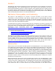
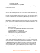
Abstract This whitepaper discusses the networking technology behind Virtual Connect Ethernet as it relates to interoperability with a Cisco network infrastructure. Since Virtual Connect represents a new way of interconnecting HP Blade servers to external networks, many implementers have questions about how Virtual Connect will integrate into their existing Cisco network infrastructure.
Ethernet components and technology. The subsequent sections will be devoted to covering the details of many networking features where Virtual Connect and the external Cisco infrastructure intersect.
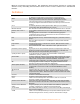
VC Uplink VLAN Trunk XFP console. Visible ports on the VC-Enet module faceplate that provide external connectivity for the enclosure. A single physical port or a single port channel with VLAN tagging enabled. Used to provide connectivity to one or more VLANs over the same logical path. A hot-pluggable modular 10 Gbit port.
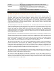
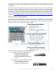
Figure 1. Overview of c7000 Enclosure Components c-Class Cabling Layout The c-Class server blades use various mezzanine cards to connect to different network fabrics through the interconnect bays at the rear of the enclosure. These fabrics include Ethernet, Fiber Channel, Infiniband, etc. The mezzanine cards are inserted in the mezzanine slots in the blade server.
using all Ethernet, is a total of 16 NICs, where two NIC ports are connected to each of the eight interconnect bays. Mezzanine slots may be populated with I/O technologies other than Ethernet (such as Fibre Channel or InfiniBand), but this paper focuses primarily on Ethernet. Figure 2.
c-Class Ethernet Interconnect Options The BladeSystem c7000 Enclosure offers a variety of interconnect options, including pass-thru modules, Ethernet and Fibre Channel switches, Virtual Connect modules, and high-bandwidth fabrics such as InfiniBand. The HP website (www.hp.com/go/bladesystem/interconnects) contains the most up-to-date information about the available c-Class interconnect modules.
configuration, the Virtual Connect Manager can deploy and move a server profile to any server bay within the Virtual Connect domain without the need to change external LAN or SAN configurations.
o 2 x 10Gb SR or LR fiber uplinks (XFP) o 2 x 1Gb fiber uplinks (SFP) o 4 x 1Gb (1000/100/10)copper uplinks (RJ-45) The purpose of the Virtual Connect Manager (VCM) is to function as the single point of administration for the Virtual Connect Domain. This means that all aspects of configuring, managing, and monitoring the Virtual Connect Domain and all VC Ethernet and Fiber Channel modules is provided by VCM.
identified by a unique identifier called Object ID. Basic SNMP support is provided for VC-Enet modules.
external devices or to provide connectivity between two external networks. Virtual Connect is not, and can not be configured as, a transit device. In other words, VC can only provide internal connectivity between blade servers and\or VC can provide external connectivity to blade servers but Virtual Connect cannot provide connectivity between two external devices.
the Administrator can choose fault tolerance plus load balancing by setting the vNet’s connection mode to “Auto”. When an administrator assigns multiple VC uplinks to the same vNet, VC’s default behavior (connection mode ‘auto’) for a vNet (or Shared Uplink Set) is to attempt to negotiate a port channel (EtherChannel) using 802.3ad Link Aggregation Control Protocol (LACP). If LACP negotiation fails, the vNet operates in fault tolerance mode only.
configured on all the uplinks associated with the vNet, the server connectivity should be restored in under five seconds. If the previous active uplink has it’s link restored, VC will automatically failback to it. As long as the external Cisco switch port has been properly configured by enabling PortFast, connectivity to servers should be restored in under five seconds. Virtual Connect uses a mechanism called “Fast MAC Cache Failover” to proactively update the CAM tables on the upstream Cisco switch ports.
between the VC Ethernet module and the external switch. A vNet may form more than one port channel with an external switch or switches. Each port channel behaves as a single logical path. Like in the previous section describing simple fault tolerance, a vNet can only have one active logical path at any given time. As such, a vNet with multiple port channels will only use one port channel as the active logical path and all other port channels in the same vNet will be in standby mode.
• • • • • • Identifies all conversations coming from the same MAC address and load balances them all down a single link in the port channel Destination MAC address Identifies all conversations destined for the same MAC address and load balances them all down a single link in the port channel Source IP address Identifies all conversations coming from the same IP address and load balances them all down a single link in the port channel Destination IP address Identifies all conversations destined for the same
VC Uplinks and VLAN Trunking Virtual Connect supports VLAN tagging (trunking) on VC uplinks using IEEE 802.1Q and can be configured to support VLAN tagging on blade server NIC ports. VC Uplinks can operate in one of three modes: • VLAN trunking mode o Shared Uplink Set (SUS) plus tagging on external switch port o When a VC uplink is a member of a SUS and is connected to a VLAN trunk port on an external switch, it operates as a VLAN trunk port.
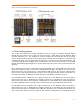
of the external switch port, a single vNet could represent a single VLAN or a single vNet could represent multiple VLANs. Figure 6. VLAN Tagging Examples (see Appendix A for a description of the elements in the above diagram) Explanation of the Figure Above: • VC Uplink 3 is assigned to a Shared Uplink Set (SUS) and is tagged with VLANs 2 thru 4.
Shared Uplink Sets manage uplink redundancy the same as individual vNets do. In other words, when multiple uplinks are assigned to a Shared Uplink Set, the uplinks can operate in failover-only mode or they can operate in port channeling (EtherChannel) mode. Also, all VLANs and associated vNets within a single Shared Uplink Set use the same active uplink or same active port channel.
vNets and EtherChannel” for an example). HP recommends that SmartLink only be enabled on a vNet if ALL server NIC ports assigned to the vNet are using NIC Teaming and are connected to at least one other vNet. For additional information on NIC Teaming for Windows, see link in the “Additional Resources” section at the end of this paper. Virtual Connect and Cisco Terminology Comparison In addition to using many traditional networking terms, Virtual Connect also introduces some new networking terminology.
Cisco Configuration Guidelines for VC Uplink Ports VLAN Tagged VC Uplink (Shared Uplink Set) Configuration Guidelines: Action • Set VLAN encapsulation to 802.
Sample Virtual Connect Ethernet and Cisco Configurations The four sample configurations below are provided to give an Administrator a general understanding of how to configure their Cisco infrastructure when connected to Virtual Connect. The sample configurations start simple and increase in complexity – basic fault tolerance, then VLAN trunking, then port channeling, then port channeling plus VLAN trunking.
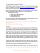
description "VC2 Uplink 1" switchport mode access switchport access vlan 1 spanning-tree portfast ! interface GigabitEthernet0/4 description "VC2 Uplink 2" switchport mode access switchport access vlan 1 spanning-tree portfast Sample Configuration 2: VC Uplinks Connected to Cisco VLAN Trunk Ports The figure below shows a VC and Cisco VLAN Trunking scenario and the minimum configuration required on the Cisco switch.
spanning-tree portfast trunk ! interface GigabitEthernet0/2 description "VC1 Uplink 2, Po1" switchport trunk encapsulation dot1q switchport trunk allowed vlan 2,3,4 switchport mode trunk spanning-tree portfast trunk ! interface GigabitEthernet0/3 description "VC2 Uplink 1, Po2" switchport trunk encapsulation dot1q switchport trunk allowed vlan 2,3,4 switchport mode trunk spanning-tree portfast trunk ! interface GigabitEthernet0/4 description "VC2 Uplink 2, Po2" switchport trunk encapsulation dot1q switchpor
Figure 9.
channel-group 2 mode active spanning-tree portfast Note: The PortFast command in this scenario is only required under the Port Channel interfaces and is not required on the physical interfaces. However, best practice is to include the PortFast command under the physical interface just in case the port channel is dissolved and the uplinks resort to simple failover mode.
description "Port Channel to VC2" switchport trunk encapsulation dot1q switchport trunk allowed vlan 2,3,4 switchport mode trunk spanning-tree portfast trunk ! interface GigabitEthernet0/1 description "VC1 Uplink 1, Po1" switchport trunk encapsulation dot1q switchport trunk allowed vlan 2,3,4 switchport mode trunk channel-protocol lacp channel-group 1 mode active spanning-tree portfast trunk ! interface GigabitEthernet0/2 description "VC1 Uplink 2, Po1" switchport trunk encapsulation dot1q switchport trunk
using different vNets for the same VLAN, an administrator can control traffic flow on a per server NIC basis. Below are some examples. Advanced VC-Enet Designs: Example Design #1 Referring to Figure 12, an administrator could use one vNet (VC_LAN_1_A) to couple a NIC on Server 1 and a NIC on Server 2 with a VC uplink that is connected to an external switch port assigned to VLAN 1. In this case, VC_LAN_1_A represents VLAN 1 within the VC Domain.
for the vNet and the port channel will be active. As a result, both port channels are active. No loop results since VC does not permit frames to jump between vNets. Since both port channels are active, the VC Domain has a 4 Gb connection to VLAN 1 (2 port channels x 2 Gb each). In order to utilize both port channels, the servers can be divided between the two vNets or each server can be connected to both vNets using NIC Teaming (as the figure below depicts).
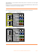
shared 4 Gb connection (2 port channels x 2 Gb each) to provide blade server connectivity to VLAN 2 thru 4. In order to utilize both port channels, the servers can be divided between the vNets associated with each Shared Uplink Set or each server can be connected using NIC Teaming (as the figure below depicts) to vNets from both Shared Uplink Sets that represent the same external VLAN. For example, blade server 1 has one NIC assigned to VC_LAN_4_A and one assigned to VC_LAN_4_B.
NIC ports are assigned to the same vSwitch on the ESX server. This allows the vSwitch to use either NIC port to reach any of the VLANs over an active 2 Gb logical path. VLANs 2 thru 4 are represented within this VC domain by two active 2 Gb port channels for a total of 4 Gb. Figure 14.
Comparing VC and VMware Networking Technology One method of understanding how Virtual Connect operates on the LAN is to compare the Virtual Connect networking components and their functionality to the networking components of a VMware ESX server.
Figure 15. VMware ESX server Compared to Virtual Connect Enclosure After comparing the components and their functionality, it is obvious why many customers treat a cClass enclosure with Virtual Connect the same way they would a single VMware ESX server. In other words, VC allows an entire enclosure to look to the network just like a big VMware ESX server. From a network redundancy and load balancing perspective, from a security perspective, from a port monitoring perspective, etc.
Provides load balanced external connectivity for internal servers 3 3 External network sees multiple MAC addresses on pNICs (VMware) or VC Uplinks 3 3 (from VMs) (from blade servers) Can be configured to isolate internal servers into separate Layer 2 domains (broadcast domains) 3 3 Can be configured to allow internal servers to communicate directly 3 3 pNICs\VC Uplinks can be configured as Port Trunks (EtherChannel) 3 3 pNICs\VC Uplinks can be configured as VLAN Trunks 3 3 Does NOT trans
Virtual Connect’s Loop Prevention Technology Virtual Connect’s loop prevention technology is best described by building on what was discussed in the section above, “Comparing VC and VMware Networking Technology”. VC’s loop prevention technology is very similar to the NIC Teaming\bonding technology used by ProLiant servers.
Figure 16. VC Stacking Link Minimum Recommendations Optimizing Virtual Connect Stacking Links Virtual Connect stacking links provide the physical path between downlinks (server NIC ports) to VC uplinks. As a result, the fewer VC uplinks a frame has to traverse, the less latency the frame incurs in reaching the external network. Each VC module a frame must traverse adds approximately 3.8 microseconds of latency to the frame.
VC Managed MAC Addresses One of the many features provided by Virtual Connect is the ability to “manage” the blade server MAC addresses. Specifically, Virtual Connect ‘manages’ the blade server MAC addresses. Virtual Connect does not ‘virtualize’ the blade server MAC addresses. Many VC implementers don’t appreciate the difference between ‘virtualized’ MAC addresses and ‘managed’ MAC addresses. A ‘virtualized’ MAC address is a MAC address that is not really owned and used by a physical NIC.
• Static, factory-default MAC addresses As the name suggests, this setting tells Virtual Connect to not manage the server MAC addresses. The server will only use the original factory burned-in MAC address. • User-defined This setting allows the Administrator to define a Locally Administered MAC address range that Virtual Connect will use to assign to blade servers.
PortFast The Spanning Tree PortFast feature was designed for Cisco switch ports connected to edge devices, like server NIC ports. This feature allows a Cisco switch port to bypass the ‘listening’ and ‘learning’ stages of spanning tree and quickly transition to the ‘forwarding’ stage.
Quality of Service In the current version of firmware, Virtual Connect does not support any user-configurable settings for traffic classification, marking, or prioritization. In addition, VC does not utilize layer 2 quality of service markings (802.1p Class of Service) nor layer 3 quality of service markings (TOS, DSCP) for frame prioritization. However, just like with any server-to-Cisco-switch deployment, QoS settings can be applied to the Cisco switch port connected to VC uplinks.
Figure 17. Using multiple vNets to force server-to-server traffic through external Cisco switch Port Security Many network administrators use a Cisco switch feature called “Port Security” to provide additional security on the network. This feature allows the administrator to control how many MAC address are learned on a particular switch port or allows the administrator to limit connectivity to specific MAC addresses.
addresses with a user-defined range will simply the task. Simply configure port security to allow the same range of MAC addresses that are manually configured for the user-defined range. Whether an administrator is configuring port security to allow a certain number of MAC address or to allow specific MAC addresses, they must configure all Cisco ports assigned to the same vNet (or Shared Uplink Set) with the same port security settings in order to eliminate communication problems after a VC uplink failover.
Figure 18. Using multiple vNets to extend PVLAN configuration from external Cisco switch (Please refer to Cisco documentation for a discussion of isolated, promiscuous, and community VLANs) Multicast & IGMP Snooping The IGMP Snooping feature allows VC-Enet modules to monitor (snoop) the IGMP membership activities of the blade servers and optimize a vNet’s handling of multicast traffic to maximize network resource utilization. Currently only IGMP v1 and v2 (RFC2236) are supported.
The monitor session must be configured with at least one ‘monitored port’ and a single ‘analyzer port’. The ‘monitor port’ list is the list of server downlinks whose traffic will be mirrored. The ‘analyzer port’ is the VC uplink port that the network analyzer is connected to. VC will mirror the traffic from the monitored ports to the analyzer port. A Port Monitoring session can mirror the traffic for up to 16 server downlinks to the analyzer port.
Additional Resources HP Services: www.hp.com/go/bladesystem/services BladeSystem Solutions: www.hp.com/go/bladesystem/solutions Virtual Connect Cookbook: www.hp.com/go/bladeconnect (see the Virtual Connect Interest Group) Virtual Connect Documentation: www.hp.com/go/bladesystem/documentation Virtual Connect Firmware: www.hp.com/go/bladesystemupdates HP NIC Teaming for Windows Whitepaper: ftp://ftp.compaq.com/pub/products/servers/networking/TeamingWP.pdf About the Author M.
Appendixes Appendix A: Description of VC Network Diagram HP Virtual Connect for Cisco Network Administrators (version 1.
Appendix B: c3000 Port Mapping Diagram Server Bays Half-Height Server Interconnect Bays Server Bays Full-Height Server Interconnect Bays HP Virtual Connect for Cisco Network Administrators (version 1.
Appendix C: Frequently Asked Questions Q1: Why do I see lots of dropped frames (discards) on standby VC uplink ports? A1: An external switch has no concept of which VC link is the active uplink and which is the standby uplink. As far as the external switch is concerned, one of the uplinks is just a whole lot busier. That means that the external switch is still going to send some types of frames down the standby link and the standby link is going to discard them.
A10: No. Regardless of which VC module is running the active Virtual Connect Manager, all VC modules can be used simultaneously to provide network connectivity. Q11: Does VC support iSCSI? A11: Yes VC is compatible with iSCSI. Since VC is a layer 2 device and iSCSI is an upper layer protocol, above TCP/IP, VC does not implement any features specific to iSCSI. However, VC can provide network connectivity for a server running iSCSI just like any other protocol.
IPX, AppleTalk, etc.? A25: Virtual Connect only supports IP (IPv4) on its management interfaces (Web, SSH CLI, or SNMP). In reference to Virtual Connect’s bridging functionality, VC supports any layer 3 or higher protocol in use on blade servers. Since Virtual Connect is a layer 2 device, it is layer 3 protocol agnostic. Meaning, the blade servers can communicate through VC using any upper layer protocol (e.g. IPv4, IPv6, IPX, AppleTalk, etc.) that’s carried within an Ethernet frame.