
User Guide
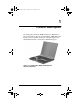
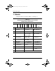
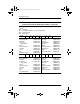
Table Of Contents
- Contents
- Product Description
- Troubleshooting
- Illustrated Parts Catalog
- Removal and Replacement Preliminaries
- Removal and Replacement Procedures
- 5.1 Serial Number
- 5.2 Disassembly Sequence Chart
- 5.3 Preparing the Computer for Disassembly
- 5.4 Computer Feet
- 5.5 Memory Expansion Board
- 5.6 Mini PCI Communications Board
- 5.7 Disk Cell RTC Battery
- 5.8 Connector Cover
- 5.9 LED Cover
- 5.10 Keyboard
- 5.11 Heat Spreader
- 5.12 Processor
- 5.13 Display
- 5.14 Palm Rest
- 5.15 Diskette Drive
- 5.16 TouchPad Components
- 5.17 Display Release Assembly
- 5.18 Charger Board
- 5.19 Speaker Assembly
- 5.20 Top Cover
- 5.21 Fan
- 5.22 System Board
- 5.23 Modem Cable
- Specifications
- Connector Pin Assignments
- Power Cord Set Requirements
- Screw Listing
- Index

1–2 Maintenance and Service Guide
Product Description
1.1 Models
Computer models are shown in Tables 1-1 through 1-3.
Table 1-1
Compaq Evo Notebook N1005 and Presario 900
Model Naming Conventions
Key
P900 P 220 P5 40 V C 51 O XXXXXX-XXX
123456789 10
Key Description Options
1 Brand/Series
designator
E = Evo
P = Presario
1005 = 1005 Series
900 = 900 Series
2 Processor type A = AMD Athlon XP+ D = AMD Duron
3 Processor speed 153 = 1.53 GHz
147 = 1.47 GHz
140 = 1.40 GHz
130 = 1.30 GHz
120 = 1.20 GHz
4Display type/
size/resolution
X = XGA
(1024 × 768)
5 = 15.x-inch
4 = 14.x-inch
5 Hard drive size 40 = 40 GB
30 = 30 GB
20 = 20 MB
6 Optical drive
designator
V = DVD-ROM drive
W = DVD-RW drive
D = CD-ROM drive
R = CD-RW drive
7 Integrated
communication
M = Modem
0 = None
C = Modem/NIC
combination card
8 RAM 51 = 512 MB 25 = 256 MB
9 Operating system O = Windows XP Pro E = Windows XP
Home
10 SKU#
272638-001.book Page 2 Thursday, July 25, 2002 4:21 PM