Notice The information in this guide is subject to change without notice. Compaq Computer Corporation shall not be liable for technical or editorial errors or omissions contained herein; nor for incidental or consequential damages resulting from the furnishing, performance, or use of this material. This guide contains information protected by copyright. No part of this guide may be photocopied or reproduced in any form without prior written consent from Compaq Computer Corporation.
Preface This Maintenance and Service Guide is used for reference when servicing the Compaq Contura Aero Family of Personal Computers.
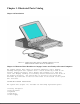
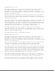
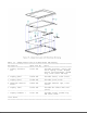
Chapter 1. Illustrated Parts Catalog Chapter 1.0 Introduction Chapter 1.1 Illustrated Parts Breakdown: Compaq Contura Aero Family Of Personal Computers The Compaq Contura Aero Family of Personal Computers joins a display assembly and system unit together with a clutch secured by screws in the chassis, display enclosure, and a display pin allowing it to open and close. The display assembly is secured by screws installed in the front of the display enclosure.
o o o o PCMCIA ejector rails Trackball assembly Memory expansion board (optional) System board The keyboard is secured to the system unit with four screws and a hook latch in the front. Once the screws are removed, the keyboard must be rotated from the rear forward to disengage it from the hook latch. The keyboard must be removed to allow access to any of the system board components. The keyboard is connected to the system board with two ribbon cables and zero insertion force (ZIF) connectors.
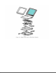
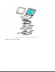
Compaq Contura Aero 4/25 The display assembly is secured with two screws in the bottom corners of the display bezel and by a screw in a clutch and a pin to the base enclosure. To remove the display assembly from the base enclosure, the display bezel must be removed first. Then the CPU cover is removed to allow access to the system board. The monochrome LCD is secured to the display enclosure with two screws in the top left corner and one screw in the top right corner.
Chapter 1.
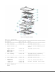
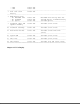
Table 1-1. System Unit =========================================================================== Description Spare Part No. Notes =========================================================================== 1 Base enclosure 197253-001 Includes screw covers. --------------------------------------------------------------------------2 System board, 4 MB Does not include PCMCIA ejector rails. Compaq Contura 197241-001 Includes screw covers.
- 4 MB 190565-001 - 8 MB 190596-001 --------------------------------------------------------------------------7 Real time clock 117099-001 battery --------------------------------------------------------------------------8 NiMH Battery Pack - 8A: Extended Life 190626-001 Extended Life battery does not - 8B: Standard 190697-001 include spacer. Standard battery - 8C: Spacer 197317-001 includes spacer.
Table 1-2. Compaq Contura Aero 4/25 Monochrome VGA Display =========================================================================== Description Spare Part No. Notes =========================================================================== 1 Display enclosure 197237-001 Includes enclosure, clutch, pin, kit latch, spring, screws, display shield, slotted bushing, ground clip, screw covers and logo.
Table 1-3. Compaq Contura Aero 4/33C Color VGA Display =========================================================================== Description Spare Part No. Notes =========================================================================== 1 Display enclosure 199257-001 Includes enclosure, clutch, pin, kit latch, spring, screws, display shield, slotted bushing, screw covers and logo.
Chapter 1.4 Keyboards Table 1-4. Notebook Keyboards =========================================================================== Description Spare Part Number =========================================================================== 1 U.S. 190620-001 2 U.K.
=========================================================================== Description Spare Part Number =========================================================================== 1 Enhanced II Keyboard U.S. 112573-001 (No longer available)* 2 Enhanced III Keyboard U.K.
Table 1-6. Cables =========================================================================== Description Spare Part Number =========================================================================== 1 Display Cable (Compaq Contura Aero 4/25) 197238-001 2 Trackball/Speaker Cable 197312-001 3 Communication Cable 197318-001 4 Display Cable (Compaq Contura Aero 4/33C) 199258-001 =========================================================================== Chapter 1.
Table 1-7. AC Adapter and Power Cord =========================================================================== Description Spare Part Number =========================================================================== 1 AC Adapter 190621-001 2 Power Cord (U.S./Canada) 197230-001 3 Power Cord (U.K.
--------------------------------------------------------------------------COMPAQ SERVICE QUICK REFERENCE GUIDE 106854-001 --------------------------------------------------------------------------LOTUS ORGANIZER MANUAL English 137885-001 German 137885-041 French 137885-051 Italian 137885-061 Spanish 137885-071 --------------------------------------------------------------------------Online USER'S GUIDE English 190512-001 German 190512-041 French 190512-051 Italian 190512-061 Spanish 190512-071 -------------
=========================================================================== Description Type Where Used Part Number Drive Qty =========================================================================== M2.5 x 7.0 * Hex System board to 139576-004 3/16 2 chassis --------------------------------------------------------------------------M2.5 x 3.
CPU enclosure feet 197345-001 Battery and memory doors 197239-001 PCMCIA eject rails 197314-001 Carton, quantity 5 137863-001 Carton and buns, quantity 1 137864-001 Display connector slider 140071-001 Plate logo 197251-001 Battery spacer 197317-001 ===========================================================================
Chapter 2. Service Preliminaries Chapter 2.0 Introduction This chapter provides general service information for the computer and the base unit. Adherence to the procedures and precautions described in this chapter is essential for proper service. Chapter 2.1 Electrostatic Discharge (International) A sudden discharge of static electricity from a finger or other conductor can destroy static sensitive devices or micro circuitry. Often the spark is neither felt or heard, but damage occurs.
structure determine the degree of sensitivity. The following proper packaging and grounding precautions are necessary to prevent damage: o Protect all electrostatic parts and assemblies with conductive or approved containers or packaging. o Keep electrostatic sensitive parts in their containers until they arrive at static free stations. o Place items on a grounded surface before removing them from their container. o Always be properly grounded when touching a sensitive component or assembly.
To prevent static damage at the workstation, use the following precautions: o Cover the workstation with approved static dissipative material. Provide a wrist strap connected to the work surface and properly grounded tools and equipment. o Use static dissipative mats, heel straps, or air ionizers to give added protection. o Handle electrostatic sensitive components, parts, and assemblies by the case or PCB laminate. Handle them only at static free workstations.
o Conductive bins, and other assembly or soldering aids o Conductive foam o Conductive table top workstations with ground cord of 1 megohm of resistance o Static dissipative table or floor mats with hard tie to ground o Field service kits o Static awareness labels o Wrist straps and footwear straps providing 1 megohm +/- 10% resistance o Material handling packages o Conductive plastic bags o Conductive plastic tubes o Conductive tote boxes o Metal tote boxes o Opaque shielding bags o Transparent metallized
Screws The screws used in these products are not interchangeable. If an incorrect screw is used during the reassembly process, it could cause damage to the unit. Compaq strongly recommends that all screws removed during the disassembly process be kept with the part that was removed, then returned to their proper locations. IMPORTANT: As each subassembly is removed from the computer, it should be placed away from the work area to prevent damage.
Plastics The plastics used can be damaged by application of excessive force during disassembly and reassembly. When handling the plastic cases and housing assemblies, use care. Do not use screwdrivers or similar tools to pry apart plastics. Where necessary, use the Case utility tool (spare part number 119070-001). Proper handling of this tool is illustrated in the disassembly and reassembly procedures. Disposal of a Used Battery Battery components are considered environmentally harmful.
A sudden discharge of static electricity from a finger or other conductor can destroy static sensitive devices or micro circuitry. Often the spark is neither felt or heard, but damage occurs. An electronic device exposed to electrostatic discharge (ESD) may not be affected at all and will work perfectly throughout a normal cycle. Or it may function normally for a while, then degrade in the internal layers, reducing its life expectancy.
o Place reusable electronic sensitive parts from assemblies in protective packaging or conductive foam. Use transporters and conveyors made of antistatic belts and metal roller bushings. Mechanized equipment used for moving materials must be wired to ground and proper materials selected to avoid static charging. When grounding is not possible, use an ionizer to dissipate electric charges.
o Turn off power and input signals before inserting and removing connectors or test equipment. o Use fixtures made of static safe materials when fixtures must directly contact dissipative surfaces. o Keep work area free of nonconductive materials such as ordinary plastic assembly aids and Styrofoam. o Use field service tools, such as cutters, screwdrivers, vacuums, that are conductive. o Use a portable field service kit with a static dissipative vinyl pouch that folds out of a work mat.
o Material handling packages o Conductive plastic bags o Conductive plastic tubes o Conductive tote boxes o Metal tote boxes o Opaque shielding bags o Transparent metallized shielding bags o Transparent shielding tubes SERVICE CONSIDERATIONS Listed below are some of the considerations that should be kept in mind during the disassembly and assembly of the computer.
Cables and Connectors Most cables used throughout the unit are flex cables (Figures 2-1, 2-2, 2-3). These cables must be handled with extreme care to avoid damage. Apply only the tension required to seat or unseat the cables during insertion or removal from the connector. Handle cables by the connector or pull tabs whenever possible.
Plastics The plastics used can be damaged by application of excessive force during disassembly and reassembly. When handling the plastic cases and housing assemblies, use care. Do not use screwdrivers or similar tools to pry apart plastics. Where necessary, use the Case utility tool (spare part number 119070-001). Proper handling of this tool is illustrated in the disassembly and reassembly procedures. Disposal of a Used Battery Battery components are considered environmentally harmful.
In the interest of our customers and the protection of our environment, Compaq has initiated a disposal/recycling program for these battery packs. Further, because Compaq is funding all costs associated with the program, it is offered at no cost to the Compaq laptop and notebook customer. IMPORTANT: Toll Free Number (U.S) 1-800-524-9859, (Canada) 1-800-263-5868 Customers in North America can take advantage of this program immediately.
Chapter 3. Removal and Replacement Procedures Chapter 3.0 Introduction This chapter provides subassembly/module level removal and replacement procedures for the Compaq Contura Aero Family of Personal Computers. After completing all necessary removal and replacement procedures, run the diagnostics program to verify that all components operate properly. Chapter 3.1 Replacement Procedures For replacement procedures, follow the removal procedures in this chapter in reverse order. Chapter 3.
1. Turn off the power switch on the computer. >>>>>>>>>>>>>>>>>>>>>>>>>>>>>>>>> CAUTION <<<<<<<<<<<<<<<<<<<<<<<<<<<<<<<<< Turn off the computer before any cables are connected or disconnected. >>>>>>>>>>>>>>>>>>>>>>>>>>>>>>>>>>>>><<<<<<<<<<<<<<<<<<<<<<<<<<<<<<<<<<<<<< 2. Disconnect all external devices (diskette drive, base unit, printer, and other devices) from the computer. 3. Disconnect the power cord from the electrical outlet. 4. Disconnect the AC adapter cable from the computer. Chapter 3.
3. Remove the battery pack by gently pulling it out of the battery compartment >>>>>>>>>>>>>>>>>>>>>>>>>>>>>>>>> CAUTION <<<<<<<<<<<<<<<<<<<<<<<<<<<<<<<<< Metal objects will damage the battery pack as well as the connectors in the compartment. To prevent damage, do not let metal objects touch any of the connectors. Do not place any objects other than the battery pack in the battery compartment.
1. Align the slot in the battery pack with the rib inside the computer. 2. Insert the battery pack, with the battery contacts facing to the inside of the battery compartment. 3. Push firmly on the battery pack until it slides into place. 4. Slide the battery door on until the lock snaps into place. Chapter 3.5 Removing The Cpu Cover To remove the CPU cover, follow these steps: 1. Remove the battery pack (Figure 3-2). 2. Turn the computer upside down. 3.
6. Slide the latch on the front of the computer to the right and open the display (Figure 3-4). 7. Remove the screw covers from the bottom right and left corners of the display panel assembly. Using a Phillips screwdriver, remove the two screws (Figure 3-5).
8. Remove the bezel from the display assembly by gently pulling the bezel frame and working from the bottom up (Figure 3-6).
9. Unsnap the CPU cover with the Case utility tool and lift it off of the computer (Figure 3-7).
To replace the CPU cover, reverse the previous steps. >>>>>>>>>>>>>>>>>>>>>>>>>>>>>>>>> CAUTION <<<<<<<<<<<<<<<<<<<<<<<<<<<<<<<<< When replacing the CPU cover, be sure not to pinch the trackball cables on the right side of the cover (see Figure 3-41). >>>>>>>>>>>>>>>>>>>>>>>>>>>>>>>>>>>>><<<<<<<<<<<<<<<<<<<<<<<<<<<<<<<<<<<<<< Chapter 3.6 Removing The Keyboard To remove the keyboard, follow these steps: 1. Remove the battery pack (Section 3.4). 2. Remove the display bezel and the CPU cover (Section 3-5).
4. Gently lift up on the rear of the keyboard and unhook it from the hook latches in the front (Figure 3-9).
5. Rotate the rear of the keyboard toward you until the two ZIF connectors are exposed and lay the keyboard upside down on top of the battery compartment (Figure 3-10). NOTE: You may not have to disconnect the cables from the keyboard to have access to the component you want to remove and/or replace.
6. Using the Case utility tool, carefully lift up on the two ZIF sliders one at a time to release the keyboard cables (Figure 3-10). 7. Carefully lift the keyboard out of the computer. To replace the keyboard, reverse the previous steps. NOTE: When replacing the keyboard, position the clip on the rear of the keyboard [1] on top of the display cable ZIF slider [2] (Figure 3-10). Chapter 3.
3. Remove the keyboard (Section 3.6). 4. Release the ZIF slider attaching the display cable to the system board. NOTE: It may not be necessary to remove the display assembly from the base enclosure to service the system board. The display will support itself in an open position without falling over. 5. Remove the remaining screw on the back of the display assembly to release the clutch from the base enclosure (Figure 3-12).
>>>>>>>>>>>>>>>>>>>>>>>>>>>>>>>>> CAUTION <<<<<<<<<<<<<<<<<<<<<<<<<<<<<<<<< Do not bend the support loop. >>>>>>>>>>>>>>>>>>>>>>>>>>>>>>>>>>>>><<<<<<<<<<<<<<<<<<<<<<<<<<<<<<<<<<<<<< 6. Lift the display assembly out of the computer by sliding it to the right to pull the display pin out of the support loop. (Figure 3-13).
To replace the display assembly, follow these steps: 1. Position the display assembly by aligning the display clutch and pin with the support loop and keyed bushing (Figure 3-14).
2. Reattach the screw to the base enclosure and clutch. To reconnect the display cable to the system board, follow these steps (Figure 3-15): 1. Insert the display cable into the ZIF connector and lightly press the slider down to lock the connector. 2. Push the curved portion of the display cable inward with your finger, remove your finger, close the computer, and immediately reopen. The display cable should pop into place around the hinge forming an "S" shape.
Display Inverter Board To remove the display inverter board, follow these steps: 1. Remove the display bezel (Figures 3-5 and 3-6). 2. Remove the display cable and the backlight cable from the display inverter board in the bottom of the display enclosure by gently pulling the cables toward you, then unplugging from the inverter board LIF connector (Figure 3-16).
3. Lift the inverter board out of the display enclosure (Figure 3-17).
>>>>>>>>>>>>>>>>>>>>>>>>>>>>>>>>> CAUTION <<<<<<<<<<<<<<<<<<<<<<<<<<<<<<<<< When servicing these units, ensure that cables are placed in their proper location to avoid pinching during the reassembly process. Improper cable placement can cause severe damage to the unit.
To remove the backlit liquid crystal display (LCD) panel, follow these steps: 1. Remove the display bezel (Figures 3-5 and 3-6). 2. Remove the remaining two top left screws and the one top right screw that secure the LCD panel to the display enclosure (Figure 3-18). 3. Remove the top clutch screw and ground clip bracket in the bottom right corner of the display enclosure (Figure 3-18). 4. Carefully rotate the LCD panel to the left and out of the display enclosure (Figure 3-19).
5. Remove the display cable from the rear of the LCD panel by gently pulling the cable toward you (Figure 3-20). 6. Carefully lift up on the ZIF connector to release the display cable from the side of the LCD panel (Figure 3-20).
To replace the LCD panel, follow these steps: 1. Remove the pressure sensitive adhesive backing from the back of the display cable. Align the holes in the cable with the mounting pins on the display enclosure. 2. Connect the display cable to the LCD panel with the ZIF connector. 3. Lay the LCD panel into the display enclosure with the bottom of the display cable exposed. 4. Secure the LCD panel with three screws to the display enclosure. 5.
Pry the latch away from the display enclosure. 3. Using a Phillips screwdriver, remove the remaining screw from the clutch and then remove the clutch out of the display enclosure. 4. Remove the two screws from the pin and remove the pin from the display enclosure. 5. Remove the display shield by lifting it out of the display enclosure (Figure 3-22).
To replace the display shield, lay it inside of the display enclosure. To replace the latch, attach the spring to the latch and snap them into the display enclosure. To replace the clutch and pin, reverse the previous steps. Compaq Contura Aero 4/33C Display To remove the color VGA backlit display assembly from the Compaq Contura Aero 4/33C Personal Computer, follow these steps: 1. Remove the battery pack (Section 3.4). 2. Remove the display bezel (Figures 3-5 and 3-6). 3. Remove the CPU cover (Section 3.
6. Release the clutch from the display enclosure by removing the remaining screw on the back of the base enclosure (Figure 3-24).
>>>>>>>>>>>>>>>>>>>>>>>>>>>>>>>>> CAUTION <<<<<<<<<<<<<<<<<<<<<<<<<<<<<<<<< Do not bend the support loop. >>>>>>>>>>>>>>>>>>>>>>>>>>>>>>>>>>>>><<<<<<<<<<<<<<<<<<<<<<<<<<<<<<<<<<<<<< 7. Lift the display panel assembly out of the computer by sliding it to the right to pull the display pin out of the support loop (Figure 3-25).
To replace the display panel assembly, follow these steps: 1. Position the display assembly by aligning the display clutch and pin with the support loop and keyed bushing (Figure 3-26).
2. Reattach the screw to the base enclosure and clutch. To reconnect the display cable to the system board, follow these steps (Figure 3-27): 1. Insert the display cable into the ZIF connector and lightly press the slider down to lock the connector. 2. Push the curved portion of the display cable inward with your finger, remove your finger, close the computer, and immediately reopen. The display cable should pop into place around the hinge forming an "S" shape.
Display Inverter Board To remove the display inverter board, follow these steps: 1. Remove the display bezel (Figures 3-5 and 3-6). 2. With a Phillips screwdriver, remove the three screws that secure the inverter board to the display enclosure (Figure 3-28).
3. Gently lift the inverter board out of the display enclosure and unplug the display cable and the backlight cable (Figure 3-29).
>>>>>>>>>>>>>>>>>>>>>>>>>>>>>>>>> CAUTION <<<<<<<<<<<<<<<<<<<<<<<<<<<<<<<<< When servicing these subassemblies, ensure that cables are placed in their proper location to avoid pinching during the reassembly process. Improper cable placement can cause severe damage to the computer.
Liquid Crystal Display Panel To remove the backlit liquid crystal display (LCD) panel, follow these steps: 1. Remove the display bezel (Section 3.5). 2. Remove the remaining four screws that secure the LCD panel to the display enclosure and carefully bend back the tabs that secure the display shield to the LCD panel (Figure 3-30). 3. Carefully rotate the LCD panel to the left and out of the display enclosure (Figure 3-31).
4. Remove the display cable from the rear of the LCD panel by gently pulling the cable toward you (Figure 3-32). 5. Carefully lift up on the ZIF connector to release the display cable from the side of the LCD panel (Figure 3-32).
To replace the LCD panel, follow these steps: 1. Remove the pressure sensitive adhesive backing from the back of the display cable. Align the holes in the cable with the mounting pins on the display enclosure. 2. Connect the display cable to the LCD panel by inserting it into the ZIF connector. 3. Lay the LCD panel into the display enclosure with the bottom of the display cable exposed.
4. Carefully press down the tabs of the display shield back into place. 5. Secure the LCD panel with four screws to the display enclosure. Latch, Clutch, Pin, and Display Shield To remove and replace the latch, the clutch, and display shield from the display assembly, follow these steps: 1. Remove the remaining four screws that secure the LCD panel to the display enclosure and carefully bend back the tabs that secure the display shield to the LCD panel and remove the LCD panel (Figures 3-30, 3-31). 2.
4. Using a small flat bladed screwdriver, remove the spring from the latch. Pry the latch away from the display enclosure [1] (Figure 3-35). 5. Remove the clutch [2] and the pin [3] out of the display enclosure (Figure 3-35).
To replace the display shield, lay it inside of the display enclosure. To replace the latch, attach the spring to the latch and snap them into the display enclosure. Chapter 3.8 Removing The DC-DC Power Supply >>>>>>>>>>>>>>>>>>>>>>>>>>>>>>>>> CAUTION <<<<<<<<<<<<<<<<<<<<<<<<<<<<<<<<< Before removing the CPU cover, be sure the AC Adapter is unplugged and the battery pack is removed from the battery compartment. If the battery pack remains in the battery compartment, it will damage the power supply.
5. Remove the threaded standoff that secures the power supply (Figure 3-36). 6. Gently grasp the power supply and pull up to unplug (Figure 3-36). To replace the power supply, reverse the previous steps. Chapter 3.9 Removing The Trackball/Buttons/Speaker Assembly To remove the trackball, follow these steps: 1. Remove the battery pack (Section 3.4). 2. Remove the display bezel (Figures 3-5 and 3-6). 3. Remove the CPU cover (Section 3.5). 4. Remove the keyboard (Section 3.6). 5.
6. With the Case utility tool, disconnect the trackball cable from the system board connector. (Figure 3-38).
7. Remove the trackball, speaker, and cable assembly. Unplug the trackball from the cable/buttons/speaker assembly (Figure 3-39).
To replace the trackball/cable assembly, follow these steps: 1. Connect the trackball to the small tab on the cable assembly (Figure 3-40).
2. Fold up the trackball and fold back the button section of the cable (Figure 3-41). 3. Place the speaker in the recessed area in the right front corner of the base enclosure and the buttons in the recessed area on the right and secure with two screws (Figure 3-41).
4. Route the speaker wires over the trackball and around the base enclosure screw hole (Figure 3-42). >>>>>>>>>>>>>>>>>>>>>>>>>>>>>>>>> CAUTION <<<<<<<<<<<<<<<<<<<<<<<<<<<<<<<<< The trackball cable and speaker wires must be routed carefully to prevent them from being pinched when the CPU cover is replaced.
5. Route the folded portion of the trackball cable behind and over the hard drive. Plug the cable into the system board LIF connector (Figure 3-43).
Chapter 3.10 Removing The Hard Drive To remove the hard drive, follow these steps: 1. Remove the battery pack (Section 3.4). 2. Remove the display bezel (Figures 3-5 and 3-7). 3. Remove the CPU cover (Section 3.5). 4. Remove the keyboard (Section 3.6). 5. Disconnect the trackball cable from the system board, but do not remove the trackball cable assembly completely (Section 3.9). 6.
8. To remove the hard drive bracket from the hard drive, with a P1 screwdriver, remove the three screws from the sides of the bracket and slip the hard drive out of the bracket. (Figure 3-45). IMPORTANT: Ensure that the screwdriver tip fits the recess properly or damage may occur to the screw head.
To replace the hard drive, follow these steps: 1. Place the hard drive inside the hard drive bracket and align the holes on the side. 2. Align the hard drive inside the bracket by inserting the screws into the holes, then tightening the screws. 3. Slide the hard drive bracket into the system chassis. >>>>>>>>>>>>>>>>>>>>>>>>>>>>>>>>> CAUTION <<<<<<<<<<<<<<<<<<<<<<<<<<<<<<<<< To prevent damage to the system board connectors ensure that the hard drive is aligned correctly.
1. Remove the battery pack (Section 3.4). 2. Remove the display bezel (Figures 3-5 and 3-6) 3. Remove the CPU cover (Section 3.5). 4. Remove the keyboard (Section 3.6). 5. Remove the power supply (Section 3.8). 6. Remove the trackball (Section 3.9). 7. Remove the hard drive (Section 3.10). 8. Using a hex socket driver, remove the six screw locks from the rear of the computer that secure the connectors to the chassis (Figure 3-46). 9.
10. Remove the two Phillips screws from the PCMCIA rails (Figure 3-48).
11. Remove the three remaining screws from the system board (Figure 3-49). NOTE: An insulator must be present under the center screw. If the insulator is not present, order a new system board.
12. Rotate the system board out of the system chassis (Figure 3-50).
13. Slide the PCMCIA rails out of the system board (Figure 3-51).
To replace the system board, reverse the previous steps. Real Time Clock Battery To remove the real time clock battery, follow these steps: 1. Remove the display bezel (Figures 3-5 and 3-6). 2. Remove the CPU cover (Section 3.5). 3. Remove the keyboard (Section 3.6). 4. Remove the real time clock battery from the system board by inserting a nonconductive probe into the battery holder and pushing back on the battery to release it (Figure 3-52).
To replace the real time clock battery, reverse the previous steps. Chapter 3.12 Removing The Chassis To remove the system chassis, follow these steps: 1. Remove the battery pack (Section 3.4). 2. Remove the display bezel (Figures 3-5 and 3-6). 3. Remove the CPU cover (Section 3.5). 4. Remove the keyboard (Section 3.6). 5. Remove the VGA backlit display. 6. Remove the power supply (Section 3.8). 7. Remove the trackball (Section 3.9). 8. Remove the hard drive (Section 3.10). 9.
base and lifting it out (Figure 3-53). To replace the system chassis, reverse the previous steps.
Chapter 4. Power On Self Test (POST) Chapter 4.0 Introduction This section lists the assemblies checked by the Power On Self Test (POST). The section also includes procedures for clearing the power on password. Chapter 4.1 POST POST is a series of diagnostic tests that run automatically when the system is turned on.
you can continue. To delete the password, type the current password immediately followed by a backslash (\) and press the Enter key. NOTE: If you don't have access to the power on password, you must disable the power on password by removing the real time clock battery. Refer to section 3.11, "Real Time Clock Battery," for removal procedures.
Chapter 5. Error Messages and Codes Chapter 5.0 Introduction This chapter contains Power On Self Test (POST) messages, Diagnostic error codes, and memory error codes. The messages and codes appear in tables that include a description of the error, the probable cause, and the recommended action that should be taken to resolve the error condition. Chapter 5.1 Power On Self Test Messages An error message results if a problem is encountered from the Power On Self Test utility.
Probable Cause: System, ROM checksum error Recommended Action: 1. Verify the correct ROM. 2. Replace the system board. --------------------------------------------------------------------------Message: 101 ROM Error Beeps: 1 Long, 1 Short (Beeps can be disabled by the user from the Computer Setup utility. Probable Cause: Second system ROM does not pass the checksum Recommended Action: 1. Verify the correct ROM. 2. Replace the system board.
Recommended Action: Replace the system board. --------------------------------------------------------------------------Message: 102 System Board Failure Beeps: None (Beeps can be disabled by the user from the Computer Setup utility. Probable Cause: DMA register read/write test failed Recommended Action: Replace the system board.
Message: 164 Memory Size Error Beeps: 2 Short (Beeps can be disabled by the user from the Computer Setup utility. Probable Cause: Increase in the memory size found compared to the one stored in CMOS Recommended Action: Run Computer Setup. --------------------------------------------------------------------------Message: 164 Memory Size Error Beeps: 2 Short (Beeps can be disabled by the user from the Computer Setup utility.
Beeps: None (Beeps can be disabled by the user from the Computer Setup utility. Probable Cause: XX000YZZ RAM failure Recommended Action: Replace the system board. --------------------------------------------------------------------------Message: 203 Memory Address Error Beeps: None (Beeps can be disabled by the user from the Computer Setup utility. Probable Cause: Memory test high address line error Recommended Action: Replace the memory expansion board (Figure 5-1).
--------------------------------------------------------------------------Message: 301 Keyboard Error Beeps: None (Beeps can be disabled by the user from the Computer Setup utility. Probable Cause: Keyboard Recommended Action: Replace the keyboard. --------------------------------------------------------------------------Message: 301 Keyboard Error Beeps: None (Beeps can be disabled by the user from the Computer Setup utility.
Recommended Action: Replace the keyboard. --------------------------------------------------------------------------Message: 301 Keyboard Error Beeps: None (Beeps can be disabled by the user from the Computer Setup utility. Probable Cause: Bad results from keyboard test Recommended Action: Replace the keyboard. --------------------------------------------------------------------------Message: 301 Keyboard Error Beeps: None (Beeps can be disabled by the user from the Computer Setup utility.
Recommended Action: 1. Replace the keyboard. 2. Replace the trackball and trackball cable. 3. Replace the system board. --------------------------------------------------------------------------Message: 304 Keyboard of System Unit Error Beeps: None (Beeps can be disabled by the user from the Computer Setup utility. Probable Cause: Keyboard Recommended Action: 1. Replace the keyboard. 2. Replace the trackball and trackball cable. 3. Replace the system board.
Probable Cause: Hard drive format error Recommended Action: 1. Run Computer Checkup (TEST). 2. Replace the hard drive. --------------------------------------------------------------------------Message: 1781 Disk 1 Failure Beeps: None (Beeps can be disabled by the user from the Computer Setup utility. Probable Cause: Disk 1 failed to respond Recommended Action: 1. Run Computer Checkup (TEST). 2. Replace the drive.
Beeps: None (Beeps can be disabled by the user from the Computer Setup utility. Probable Cause: Disk 1 responded with an error Recommended Action: 1. Run Computer Checkup (TEST). 2. Replace the drive. 3. Replace the system board. --------------------------------------------------------------------------Message: 1791 Disk 1 Error Beeps: None (Beeps can be disabled by the user from the Computer Setup utility. Probable Cause: Hard Drive 1 Error Recommended Action: 1. Run Computer Checkup (TEST). 2.
Table 5-2. System Test Error Codes =========================================================================== Error Code Description Recommended Action =========================================================================== 101 - xx CPU test failed Replace the system board and retest. --------------------------------------------------------------------------103 - xx DMA page registers test Replace the system board and retest.
2. Replace the system board and retest. --------------------------------------------------------------------------203 - xx Memory write/read test The following steps apply to failed 203 - xx through 211 - xx error codes: 204 - xx Memory address test failed If you don't have a memory expansion board, replace the system board. 210 - xx Increment pattern test failed If you have a memory expansion board: 211 - xx Random pattern test failed Replace the memory expansion board and retest (Figure 5-1).
602 - xx Diskette read test failed 603 - xx Diskette write, read, compare test failed 604 - xx Diskette random seek test failed 605 - xx Diskette ID media failed 606 - xx Diskette speed test failed 607 - xx Diskette wrap test failed 608 - xx Diskette write protect test failed 609 - xx Diskette reset controller test failed 610 - xx Diskette change line test failed 697 - xx Diskette type error 2. Check and/or replace the diskette power and signal cables and PCMCIA external diskette drive.
1204 - xx Modem Auto Originate Test 1206 - xx Dial Multifrequency Tone Test 3. Replace the modem and retest. 1210 - xx Modem Direct Connect Test =========================================================================== Table 5-9.
test failed 1719 - xx Hard drive power mode test failed 1799 - xx Invalid hard drive type failed --------------------------------------------------------------------------* Error Correction Code =========================================================================== Table 5-10.
2419 - xx ECG/VGC ROM checksum test failed 2421 - xx ECG/VGC 640 x 200 graphics mode test failed 2422 - xx ECG/VGC 640 x 350 16 color set test failed 2423 - xx ECG/VGC 640 x 350 64 color set test failed 2424 - xx ECG/VGC monochrome text mode test failed 2425 - xx ECG/VGC monochrome graphics mode test failed 2431 - xx 640 x 480 graphics test failure 2432 - xx 320 x 200 graphics (256 color mode) test failure 2448 - xx Advanced VGA Controller test failed 2451 - xx 132 column Advanced VGA tes
2. Replace the system board and retest. =========================================================================== Table 5-12. Audio Test Error Codes =========================================================================== Error Code Description Recommended Action =========================================================================== 3206 - xx Audio System Internal Replace the system board and retest.
Chapter 6. Specifications Chapter 6.0 Introduction This chapter provides physical, environmental, and performance specifications for the following Compaq Contura Aero Family of Personal Computer subsystems: o o o o o o o o Computer VGA Display Hard Drives Internal Power Supply NiMH Battery Pack AC Adapter Base Unit External Diskette Drive Chapter 6.1 System Unit =========================================================================== U.S.
Nonoperating 60g, 11ms, half sine Vibration Operating 0.25g, 5-500 Hz 1/2 octave/min sweep, 1 hour duration Nonoperating 1.00g, 5-500 Hz 1/2 octave/min sweep, 1 hour duration --------------------------------------------------------------------------Maximum Altitude (unpressurized): Operating 10,000 ft 3,658m Nonoperating 30,000 ft 12,192m =========================================================================== Chapter 6.
Mounting Internal --------------------------------------------------------------------------Display CSTN Backlit LCD --------------------------------------------------------------------------Color Resolution 256 Colors - low resolution 16 Colors - high resolution --------------------------------------------------------------------------Brightness/Contrast Adjustable through keyboard --------------------------------------------------------------------------Maximum Pixel Resolution 640 x 480 -----------------
--------------------------------------------------------------------------Logical Configuration: Cylinders 873 722 Heads 16 10 Sectors/Track 24 23 Bytes Per Sector 512 512 =========================================================================== Chapter 6.4 Internal Power Supply =========================================================================== Input Requirements: Input Voltage 10.8 - 17.5 VDC Standby 10.8 - 17.
Standard (Metric) -20oC to 50oC Extended Life (U.S.) -4oF to 122oF Extended Life (Metric) -20oC to 50oC --------------------------------------------------------------------------* Battery life is based on an estimated typical use pattern of an average user. Battery life will vary based on the configuration of the computer and the usage pattern of the individual user. To maximize battery life, Compaq recommends that power conservation be set to high.
Vibration Operating 0.25g, 5-500 Hz/octave/min sweep Nonoperating 1.00g, 5-500 Hz/octave/min sweep --------------------------------------------------------------------------Maximum Unpressurized Altitude: Operating 10,000 ft 3,658 m Nonoperating 40,000 ft 15,750 m =========================================================================== Chapter 6.
--------------------------------------------------------------------------Acoustic Noise 33 dBA --------------------------------------------------------------------------Maximum Unpressurized Altitude: Operating 9,850 ft 3,077m Nonoperating 50,000 ft 12,308m ===========================================================================
Appendix A.1 External Connectors Table A-1.
Appendix B.1 Base Unit This appendix contains information about the base unit that is available for use with the Compaq Contura Aero Family of Personal Computers. Table B-1.
Table B-2. Base Unit External Connectors =========================================================================== Index Description =========================================================================== 1 DC Power 2 Parallel port 3 External VGA monitor 4 Serial port 5 External keyboard 6 PS/2 mouse =========================================================================== Troubleshooting the Base Unit If the battery charger does not work, follow these steps: 1.
2. Try another AC Adapter. 3. Check the battery slot and make sure it is clear. If the mouse or keyboard does not work, check to make sure they are plugged into the correct jack. If the printer or serial ports do not work, follow these steps: 1. Disconnect the computer from the base unit. 2. Connect the cables to the printer and serial ports of the computer. 3. If the ports work on the computer, the base unit is defective.
Appendix C.1 Connector Pin Assignments Parallel Connector C-1.
Serial Connector Serial Connector Pin Assignments =========================================================================== Pin Signal =========================================================================== 1 Carrier Detect 2 Receive Data 3 Transmit Data 4 Data Terminal Ready 5 Ground 6 Data Set Ready 7 Ready to Send 8 Clear to Send 9 Ring Indicator =========================================================================== External Options Connector
External Options Connector Pin Assignments =========================================================================== Pin Signal =========================================================================== 1 Not Connected 2 Ground 3 Ground 4 Serial Carrier Detect 5 Serial Ring Indicator 6 Serial Data Set Ready 7 Keyboard Data 8 Keyboard Clock 9 Mouse Clock 10 Printer Busy 11 Printer Paper Out * 12 Printer Auto Line Feed * 13 Printer Error * 14 Printer Select In * 15 Not Connected 16 Battery LED 17 CRT - Ver
23 Ground 24 Printer Strobe * 25 Ground 26 Printer Select 27 Ground 28 Printer Initialize * 29 Ground 30 Not Connected 31 Ground 32 Ground 33 Ground 34 Serial Data Term Ready 35 Ground --------------------------------------------------------------------------* Active low =========================================================================== Pin Signal =========================================================================== 36 Serial Clear To Send 37 Ground 38 Ground 39 Ground 40 Printer Data Bit 7 4
6 Data bit 7 7 Card enable 1 8 Address bit 10 9 Output enable 10 Address bit 11 11 Address bit 9 12 Address bit 8 13 Address bit 13 14 Address bit 14 15 Program/Write enable 16 Ready or busy/Interrupt request 17 Power 18 Programming and peripheral supply 1 19 Address bit 16 20 Address bit 15 21 Address bit 12 22 Address bit 7 23 Address bit 6 24 Address bit 5 25 Address bit 4 26 Address bit 3 27 Address bit 2 28 Address bit 1 29 Address bit 0 30 Data bit 0 31 Data bit 1 32 Data bit 2 33 Write protect/IO Por
63 Battery voltage detect 1/Card status changed 64 Data bit 8 65 Data bit 9 66 Data bit 10 67 Card detect 2 68 Ground ===========================================================================