
User`s guide
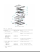

o PCMCIA ejector rails
o Trackball assembly
o Memory expansion board (optional)
o System board
The keyboard is secured to the system unit with four screws and a hook
latch in the front. Once the screws are removed, the keyboard must be
rotated from the rear forward to disengage it from the hook latch. The
keyboard must be removed to allow access to any of the system board
components. The keyboard is connected to the system board with two ribbon
cables and zero insertion force (ZIF) connectors. The cables do not
necessarily have to be disconnected to service the system board. The
keyboard may be laid on top of the battery compartment to access the system
board.
The hard drive is connected directly to the system board with no
intervening cables. It is mounted to the chassis with a hard drive bracket.
The hard drive bracket is secured to the hard drive with three screws.
The power supply is secured to the system board with one threaded standoff.
There is no cable between the power supply and the system board; the power
supply connects directly to the system board.
The trackball assembly consists of the trackball, buttons, flex cable, and
speaker. The trackball plugs directly into the cable with a low insertion
force (LIF) connector and mounts with two screws in the right front corner
of the base enclosure. The flex cable includes the buttons and speaker. The
buttons fit in a recessed area on the right side of the base enclosure and
control the functions of the trackball. The speaker is connected to the
flex cable with two wires and fits in a narrow area in the right front
corner of the base enclosure. Sound is directed through the enclosure. The
remainder of the flex cable is routed behind and over the hard drive
assembly and plugs with a LIF connector directly into the system board.
The system board is mounted directly to the chassis. All system module
components connected to the system board must be removed prior to removing
the system board.
The PCMCIA rails are secured to the system board header with two screws at
the top. The rails plug directly into the system board connector.
The memory expansion board plugs into the system board in the bottom of the
base enclosure. Remove the door, and the memory expansion board plugs into
a single connector. System memory can be increased to a maximum 12 MB by
adding an 8 MB Memory Expansion Board. A 4 MB Memory Expansion Board is
also available.
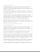
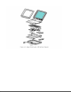
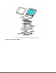
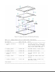
DISPLAY ASSEMBLY MODULE DESCRIPTION
The display assembly (Figures 1-5 and 1-6) includes the following
replaceable parts:
o Display bezel
o Liquid crystal display (LCD) panel
o Display inverter board
o Display cable
o Display shield
o Display enclosure