
User`s guide
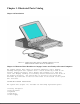

Compaq Contura Aero 4/25
The display assembly is secured with two screws in the bottom corners of
the display bezel and by a screw in a clutch and a pin to the base
enclosure. To remove the display assembly from the base enclosure, the
display bezel must be removed first. Then the CPU cover is removed to allow
access to the system board.
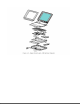
The monochrome LCD is secured to the display enclosure with two screws in
the top left corner and one screw in the top right corner. The bottom
right corner has two small cables attached to a connector for the backlight
and the inverter board.
The display cable is a flex cable plugged into a connector on the left side
of the LCD, folded, and secured to the display shield with a pressure
sensitive adhesive. One end of the display cable is exposed at the bottom
of the display enclosure and is connected to the system board with a zero
insertion force (ZIF) slider. The other end is connected with a low
insertion force (LIF) connector to the display inverter board.
The display inverter board is aligned in the bottom of the display
enclosure with pins. One end connects to the display cable; the other end
plugs into the backlight cable of the LCD panel and is held in place with
pressure sensitive adhesive tape.
The display shield lays in the display enclosure.
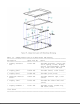
Compaq Contura Aero 4/33C
The display assembly is secured with two screws in the bottom corners of
the display bezel and by a screw in a clutch and a pin to the base
enclosure. To remove the display assembly from the base enclosure, the
display bezel must be removed first. Then the CPU cover is removed to allow
access to the system board.
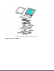
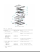
The color LCD is secured to the display enclosure with four screws in the
corners of the LCD panel. The top right corner has two small cables
attached to a connector for the backlight and the inverter board.
The display cable is a flex cable plugged into a ZIF connector on the left
side of the LCD, folded, and secured to the display shield with a pressure
sensitive adhesive. One end of the display cable is exposed at the bottom
of the display enclosure and is connected to the system board with a ZIF
connector. The other end plugs into a LIF connector on the display inverter
board in the lower right hand corner of the display enclosure.
The display inverter board is aligned on the right side of the display
enclosure and mounted component side down. One end connects to the display
cable; the other end plugs into the backlight cable of the LCD panel.
The display shield lays in the display enclosure and has tabs that bend
over the screw holes of the LCD and secure the display shield to the LCD.