b Maintenance and Service Guide Compaq Armada 110™ Document Part Number: 238850-001 April 2001 This guide is a troubleshooting reference used for maintaining and servicing the notebook. It provides comprehensive information on identifying computer features, components, and spare parts, troubleshooting computer problems, and performing computer disassembly procedures.
© 2001 Compaq Computer Corporation Compaq, the Compaq logo, Armada, Deskpro Registered in U. S. Patent and Trademark Office. Microsoft, MS-DOS, Windows, Windows NT are trademarks of Microsoft Corporation in the United States and other countries. All other product names mentioned herein may be trademarks of their respective companies. Compaq shall not be liable for technical or editorial errors or omissions contained herein.
Contents 1 Product Description 1.1 Models and Features . . . . . . . . . . . . . . . . . . . . . . . . . 1–1 Models . . . . . . . . . . . . . . . . . . . . . . . . . . . . . . . . . . . . 1–2 Features . . . . . . . . . . . . . . . . . . . . . . . . . . . . . . . . . . . 1–4 1.2 Security . . . . . . . . . . . . . . . . . . . . . . . . . . . . . . . . . . . 1–5 1.3 Power Management . . . . . . . . . . . . . . . . . . . . . . . . . . 1–6 Enabling Power Savings . . . . . . . . . . . . . . . . . . . . . .
2.9 No Operating System (OS) Loading . . . . . . . . . 2–12 2.10 No OS Loading from Hard Drive, Part 1. . . . . 2–13 2.11 No OS Loading from Hard Drive, Part 2. . . . . 2–14 2.12 No OS Loading from Hard Drive, Part 3. . . . . 2–15 2.13 No OS Loading from Diskette Drive. . . . . . . . 2–16 2.14 No OS Loading from CD- or DVD-ROM Drive. . . . 2–17 2.15 No Audio, Part 1 . . . . . . . . . . . . . . . . . . . . . . . 2–18 2.16 No Audio, Part 2 . . . . . . . . . . . . . . . . . . . . . . . 2–19 2.
Removal and Replacement Procedures 5.1 Serial Number . . . . . . . . . . . . . . . . . . . . . . . . . . . . . . 5–2 5.2 Disassembly Sequence Chart . . . . . . . . . . . . . . . . . . . 5–3 5.3 Preparing the Computer for Disassembly . . . . . . . . . 5–4 5.4 Computer Feet . . . . . . . . . . . . . . . . . . . . . . . . . . . . . . 5–5 5.5 LED Cover . . . . . . . . . . . . . . . . . . . . . . . . . . . . . . . . . 5–6 5.6 Keyboard . . . . . . . . . . . . . . . . . . . . . . . . . . . . . . . . . . 5–7 5.
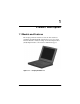
1 Product Description 1.1 Models and Features The Compaq Armada 110 Series notebook offers advanced modularity, Intel Pentium III or Intel Celeron processors with 64-bit architecture, industry-leading Accelerated Graphics Port (AGP) implementation, and extensive multimedia support. .
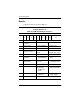
Product Description Models Computer models are shown in Table1-1. Table 1-1 Compaq Armada 110 Models and Model Naming Conventions Key A11 1 P 2 800 4X 10 V C 128 98 9L XXXXXX-XXX 4 5 6 7 8 9 10 11 3 Key Description Options 1 Brand / Series designator A=Armada 11=110 2 Processor type P=Intel Pentium III C=Intel Celeron 3 Processor speed 800=800 MHz 700=700MHz 4 Display type/size/resolution 4=14.x” 2=12.x” X=XGA (1024 × 768) S=SVGA (800 × 600) 5 Hard drive size 10=10.
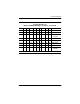
Product Description Table 1-1 Compaq Armada 110 Models and Model Naming Conventions (Continued) 1 2 3 4 5 6 7 8 9 10 11 A11 P 800 4X 10 V C 64 M L 226917-B21 A11 P 800 4X 10 D C 64 M L 226915-B21 A11 P 800 4X 10 D C 64 M L 231665-B21 (NAFTA) A11 P 800 TS 10 D C 64 M L 226918-B21 A11 C 700 TX 10 D C 64 M L 231664-B21 A11 C 700 TX 10 D C 64 M H 226919-B21 A11 C 700 TS 10 D M 64 8M H 226921-B21 A11 C 700 TS 10 D M 6
Product Description Features ■ 1–4 Processors, varying by computer model: ❏ 800-MHz Intel Pentium III Processor, with 256-KB integrated cache ❏ 700-MHz Intel Celeron Processor, with 128-KB integrated cache ■ ATI RAGE LT Pro, 4-MB SGRAM (synchronous graphics) ■ 64-MB high-performance Synchronous DRAM (SDRAM), expandable to 320 MB ■ Microsoft Windows 98 or Windows Me preinstalled ■ Displays, varying by computer model: ❏ 14.1-inch, SXGA, CTFT (1024 × 768) display, with over 16.
Product Description ■ ■ Connectors for: ❏ stereo speaker/headphone ❏ microphone ❏ universal serial bus ❏ RJ-45 network (internal network models only) ❏ RJ-11 modem ❏ keyboard/mouse ❏ AC power ❏ infrared port Stereo speakers 1.2 Security If the notebook you are servicing has a password and you know the password, follow these steps to disable or clear the password: 1.
Product Description If the notebook you are servicing has an unknown password, follow these steps to clear the password. These steps also clear CMOS. 1. Prepare the computer for disassembly. Refer to Section 5.3, “Preparing the Computer for Disassembly,” for more information. 2. Remove the disk cell RTC battery (refer to Section 5.15, “Disk Cell Real Time Clock (RTC) Battery”). 3. Wait approximately five minutes. 4. Reassemble the computer. 5. Connect AC power to the computer.
Product Description Timeout Settings Timeout functions can be set up to power down computer components by selecting the Power Schemes tab from the power application in the operating system’s Control Panel. When a component such as the monitor, hard drive, system, or video is not in use, the component powers down to conserve power. The time out interval can be set from one minute up to several hours. The component will power up again when you access it or press any key.
Product Description Standby Standby is an energy-saving feature that conserves power and reduces startup time. Standby reduces power to system components that are not being used. Standby can be initiated by you or by the system. When Standby is initiated, all work is saved in random access memory (RAM) and the screen is cleared. When work is resumed, the information returns to the screen. Refer to Section 1.4 in this chapter to identify the Power, Standby, and Hibernation controls.
Product Description 1.4 Computer External Components The external components on the display and left side of the computer are shown in Figure 1-2 and described in Table 1-2. Figure 1–2: Display and Left Side Components Table 1-2 Display and Left Side Components Item Component Function 1 Display release latch Releases the display to open the computer. 2 Infrared port Links another IrDA-compliant device for wireless communication. 3 Vent Allows airflow to cool internal components.
Product Description The computer right side and rear panel components are shown in Figure 1-3 and described in Table 1-3. Figure 1–3: Right Side and Rear Panel Components Table 1-3 Right Side and Rear Panel Components Item Component Function 1 Optical drive Accepts CD- or DVD-ROM disks, depending on the computer model. 2 Security cable slot Attaches an optional security cable to the computer. 3 Stereo speaker/ headphone jack Connects stereo speakers, headphones, headset, or television audio.
Product Description Table 1-3 Right Side and Rear Panel Components (Continued) Item Component Function 5 Keyboard/mouse connector Connects an optional full-sized keyboard or a mouse. When this connector is used, both the external and computer keyboard and pointing device are active. An optional splitter/adapter allows both an external keyboard and mouse to be used at the same time.
Product Description The computer keyboard components are shown in Figure 1-4 and described in Table 1-4.
Product Description Table 1-4 Keyboard Components Item Component Function 1 Fn key Used with hotkeys to perform preset hotkey functions. 2 Caps lock key Turns on the caps lock function. 3 F1 through F12 function keys Perform preset functions. 4 Display switch Turns off the computer display if the computer is closed while on. 5 Embedded numeric keypad Converts keys to numeric keypad. 6 Cursor control keys Move the cursor around the screen.
Product Description The components on the top of the computer are shown in Figure 1-5 and described in Table 1-5. Figure 1–5: Top Components Table 1-5 Top Components Item Component Function 1 Speakers (2) Produce stereo sound. 2 Hard drive light On: The primary hard drive is being accessed.
Product Description Table 1-5 Top Components (Continued) Item Component Function 3 Battery light Green steady: Battery charging is complete. Red steady: Battery pack is charging. Red blinking: Battery pack is being queried, computer cannot communicate with battery pack, or battery pack is bad. 4 Num lock light On: Num lock is on and the embedded numeric keypad is enabled. 5 Caps lock light On: Caps lock is on. 6 Scroll lock light On: Scroll lock is on.
Product Description The external components on the bottom of the computer are shown in Figure 1-6 and described in Table 1-6.
Product Description Table 1-6 Bottom Components Item Component Function 1 Mini PCI slot cover Contains the mini PCI modem or network interface card. 2 Fan vent Provides airflow to cool internal components. 3 Certificate of Authenticity label Contains the Product Key, which may need to be entered before using some Windows operating systems. 4 Memory expansion compartment Covers the memory expansion compartment. 5 Front label area Contains agency information.
Product Description 1.4 Design Overview This section presents a design overview of key parts and features of the computer. Refer to Chapter 3, “Illustrated Parts Catalog” and Chapter 5, “Removal and Replacement Procedures.
2 Troubleshooting Å WARNING: Only authorized technicians trained by Compaq should repair this equipment. All troubleshooting and repair procedures are detailed to allow only subassembly/module level repair. Because of the complexity of the individual boards and subassemblies, no one should attempt to make repairs at the component level or to make modifications to any printed wiring board. Improper repairs can create a safety hazard.
Troubleshooting Using the PhoenixBIOS Setup Utility The PhoenixBIOS Setup Utility (PSU) is built into the system. You can configure the system BIOS and modify or restore factory default settings, such as date and time, types of disk drives, power management, and password settings. To run PSU, press F10 during system startup. When the main screen displays, use the keyboard and arrow keys to move around the menus and make selections.
Troubleshooting Troubleshooting Flowcharts for Portable Computers Table 2-1 Troubleshooting Flowcharts Overview Section Description 2.1 Initial troubleshooting 2.2 No power, part 1 2.3 No power, part 2 2.4 No power, part 3 2.5 No power, part 4 2.6 No video, part 1 2.7 No video, part 2 2.8 Non-functioning docking station 2.9 No operating system (OS) loading 2.10 No OS loading from hard drive, part 1 2.11 No OS loading from hard drive, part 2 2.
Troubleshooting 2.1 Initial Troubleshooting Begin Troubleshooting N Go to Section 2.2, No Power Is there power? Y N Check LED board, speaker connections. Beeps, LEDs, or error Messages? N Y Go to Section 2.17, Non-Functioning Device All drives working? N Y Go to Section 2.6, No Video Is there video? (no boot) N Keyboard/ pointing device working? Y N Y Go to Section 2.9, No OS Loading Is the OS loading? N Connecting to network or modem? Y N Is there sound? Y Go to Section 2.
Troubleshooting 2.2 No Power, Part 1 No Power (Power LED is off) Remove from docking station if applicable. N N Power up on battery power? Power up on battery power? *Reset power. Y Go to Section 2.3, No Power, Part 2 Y N N Power up on AC power? Power up on AC power? *Reset power. Y Go to Section 2.4, No Power, Part 3 Y Y Power up in docking station? Done N 1. Reseat power cables in docking station and at the AC outlet. 2. Ensure AC power source is active. 3.
Troubleshooting 2.3 No Power, Part 2 Continued from Section 2.3, No Power, Part 1 Visually check for debris in battery socket and clean if necessary Y Power on? Done N Check battery by recharging, moving to another computer, or replacing it. N Power on? Replace power supply, (if applicable) Y N Done Power on? Go to Section 2.
Troubleshooting 2.4 No Power, Part 3 Continued from Section 2.3, No Power, Part 2 Plug directly into AC outlet. Y Power LED on? Done N Reseat AC adapter in computer and at power source. Y Power on? Done N N Power outlet active? External Try different outlet. Y Internal or external AC adapter? Internal N Go to Section 2.5, No Power, Part 4 Replace power cord. Power on? Y Y Power on? Replace external AC adapter.
Troubleshooting 2.5 No Power, Part 4 Continued from Section 2.4, No Power, Part 3 Open computer. Y Loose or damaged parts? N Reseat loose components and boards and replace damaged items. Close computer and retest. N Power on? 1. Internal DC-DC converter* 2. Internal AC adapter 3. Processor board* 4. System board* Y Done 2–8 Replace the following items, if applicable. Check computer operation after each replacement: * Replace these items as a set to prevent shorting out among the components.
Troubleshooting 2.6 No Video, Part 1 No Video Docking Station Standalone or Docking Station? Go to Section 2.7, No Video, Part 2 * Note: To change from internal to external display, use the hotkey combination. Standalone Internal or external display*? Y Adjust brightness. Depress lid switch to ensure operation. A Adjust brightness. Y Video OK? Done N Internal External Video OK? Y Video OK? Done Done N N Replace one at a time. Test after each item: 1.
Troubleshooting 2.7 No Video, Part 2 Continued from Section 2.6, No Video, Part 1 Remove notebook from docking station, if connected. Adjust display brightness. Check brightness of external monitor. N Y Go to “A” in Section 2.6, No Video, Part 1. Video OK? Y Video OK? Done N Check for notebook properly seated in docking station, bent pins on cable, and for monitor connection. Try another external monitor.
Troubleshooting 2.8 Non-Functioning Docking Station (if applicable) Reseat power cord in docking station and power outlet. Check voltage setting on docking station. Reinstall notebook into docking station. Y Reset monitor cable connector at docking station. Docking station operating? Done N Y Docking station operating? Done N Remove notebook, reseat all internal parts, and replace any damaged items in docking station.
Troubleshooting 2.9 No Operating System (OS) Loading Reseat power cord in docking station and power outlet. Hard drive, go to Section 2.10. Diskette drive, go to Section 2.13. CD-/DVD-ROM drive, go to Section 2.14. Network, go to Section 2.20. NOTE: Before beginning, always check cable connections, cable ends, and drives for bent or damaged pins.
Troubleshooting 2.10 No OS Loading from Hard Drive, Part 1 OS not loading from hard drive. Y Nonsystem disk message? N Go to Section 2.11, No OS Loading from Hard Drive, part 2. Reseat external hard drive. Y OS loading? Done N N Boot from CD? N Y Boot from diskette? Check the setup utility for correct booting order. Y Go to Section 2.13, No OS Loading from Diskette Drive. Change boot priority through the setup utility and reboot.
Troubleshooting 2.11 No OS Loading from Hard Drive, Part 2 Continued from Section 2.10, No OS Loading from Hard Drive, Part 1 Reseat hard drive. N 1. Replace hard drive. 2. Replace system board. CD or diskette in drive? Y Access hard drive? Y Done N Remove diskette and reboot. Run FDISK. Y Boot from hard drive? N Done N Create partition, then format hard drive to bootable C:\ prompt. Hard drive partition? Y N Boot from diskette drive? Y N Go to Section 2.
Troubleshooting 2.12 No OS Loading from Hard Drive, Part 3 Continued from Section 2.11, No OS Loading from Hard Drive, Part 2. N System files on hard drive? Install OS and reboot (see note). Y Y Y Virus on hard drive? OS loading from hard drive? Clean virus (see note). N Done N Y Run SCANDISK, check for bad sectors. Diags on diskette? Replace hard drive. N N Can bad sectors be fixed? Run diags and follow recommendations Replace hard drive. Y N Fix bad sectors.
Troubleshooting 2.13 No OS Loading from Diskette Drive Y OS not loading from diskette drive. Reseat diskette drive. OS loading? Done N Y N NonSystem Disk message? Bootable diskette in drive? N Install bootable diskette and reboot computer. Y N Go to Section 2.17, Non-Functioning Device. Boot from another device? Check diskette for system files. Try different diskette. Y Y N Diskette drive enabled in the setup utility? Enable drive and cold boot computer. Y 1. Replace diskette drive. 2.
Troubleshooting 2.14 No OS Loading from CD- or DVD-ROM Drive Y No OS loading from CD- or DVD-ROM drive. N Bootable disk in drive? Disk in drive? Install bootable disk and reboot computer. Y N Try another bootable disk. Install bootable disk. Y Boots from CD or DVD? Done N Y Boots from CD or DVD? Reseat drive. Done N N Go to Section 2.17, Non-Functioning Device. Booting from another device? Y Y Booting order correct? Clear CMOS. Refer to Section 1.2, “Security,” for instructions.
Troubleshooting 2.15 No Audio, Part 1 Y Turn up audio internally and/or externally. No audio. Audio? Done N N Y Notebook in docking station (if applicable)? N Go to Section 2.16, No Audio, Part 2. Internal audio? Undock Y Go to Section 2.16, No Audio, Part 2. Replace the following docking station components one at a time as applicable. Check after each change. 1. Reseat docking station audio cable. 2. Replace audio cable. 3. Replace speaker. 4. Replace docking station audio board. 5.
Troubleshooting 2.16 No Audio, Part 2 Continued from Section 2.15, No Audio, Part 1. N Audio driver in OS configured? Reload audio drivers. Y N Correct drivers for application? Load drivers and set configuration in OS. Y Connect to external speaker. N Audio? Y Replace audio board and speaker connections in notebook, if applicable Y Audio? Done N 1. Replace internal speakers. 2. Replace audio board, if applicable. 3. Replace system board.
Troubleshooting 2.17 Non-Functioning Device NonFunctioning Device Reseat device. Unplug the non-functioning device from the notebook, inspect cables and plugs for bent or broken pins or other damage. Y Any physical device? Fix or replace broken item. Possible bad hard drive. Replace drive. Go to Section 2.9, No OS Loading. Clear CMOS. N Reattach device. Close notebook, plug in power, and reboot. N Device boots properly? Y Done 2–20 Possible bad NIC. Replace card.
Troubleshooting 2.18 Non-Functioning Keyboard Keyboard not operating properly. Connect notebook to good external keyboard. N External device works? Replace system board. Y Reseat internal keyboard connector (if applicable). N Replace internal keyboard or cable. OK? Y Y OK? Done Done N Replace system board.
Troubleshooting 2.19 Non-Functioning Pointing Device Pointing device not operating properly. Connect notebook to good external pointing device. N External device works? Replace system board. Y Reseat internal pointing device connector (if applicable). N OK? Replace internal pointing device or cable. Y Y OK? Done Done N Replace system board.
Troubleshooting 2.20 Network or Modem Connection No network/modem connection. N Network or modem jack active? Replace jack or have jack activated. Y Y Connect to non-digital line. Digital line? N N NIC/modem configured in OS? Y Reload drivers and reconfigure. Y OK? Done N Disconnect all power from the notebook and open. Replace NIC/modem if applicable. Y Reseat NIC/modem if applicable. OK? Done N Replace system board.
3 Illustrated Parts Catalog This chapter provides an illustrated parts breakdown and a reference for spare part numbers and option part numbers. 3.1 Serial Number Location When ordering parts or requesting information, provide the computer serial number and model number located on the bottom of the computer (Figure 3-1).
Illustrated Parts Catalog 3.
Illustrated Parts Catalog Table 3-1 Spare Parts: Computer System Major Components Item Description 1 Displays Spare Part Number 14.1-inch, XGA, CTFT 12.
Illustrated Parts Catalog Computer System Major Components (continued) 3–4 Maintenance and Service Guide
Illustrated Parts Catalog Table 3-1 Spare Parts: Computer System Major Components (Continued) Item Description Spare Part Number 8 Diskette drive 233553-001 9 10-GB hard drive (hard drive bracket spared in Hardware Kit, spare part number 234005-001) 233554-001 10 Disk cell RTC battery 236359-001 Hardware Kit 234005-001 11a 11b 11c Hard drive bracket Fan bracket Optical drive alignment rail 12 Fan (fan bracket spared in Hardware Kit, item 11, spare part number 234005-001) 13 Processors 8
Illustrated Parts Catalog 3.
Illustrated Parts Catalog 3.
Illustrated Parts Catalog 3.
Illustrated Parts Catalog 3.
Illustrated Parts Catalog 3.
Illustrated Parts Catalog Table 3-6 Spare Parts: Miscellaneous (not illustrated) (Continued) Description Spare Part Number External AC adapter 50W slim AC adapter 163444-001 163444-291 Logo kit 233556-001 Memory expansion boards 256 MB 128 MB 64 MB 167136-001 135244-001 135243-001 Screw kit (includes M2.5 × 7, M2.5 × 5.5, M2.5 × 5, and M2.5 × 4.
4 Removal and Replacement Preliminaries This chapter provides essential information for proper and safe removal and replacement service. 4.1 Tools Required You will need the following tools to complete the removal and replacement procedures: ■ Magnetic screwdriver ■ Phillips P0 screwdriver ■ Tool kit (includes connector removal tool, loopback plugs, and case utility tool) 4.
Removal and Replacement Preliminaries Plastic Parts Using excessive force during disassembly and reassembly can damage plastic parts. Use care when handling the plastic parts. Apply pressure only at the points designated in the maintenance instructions. Cables and Connectors Cables must be handled with extreme care to avoid damage. Apply only the tension required to unseat or seat the cables during removal and insertion. Handle cables by the connector whenever possible.
Removal and Replacement Preliminaries ■ Before handling a drive, ensure that you are discharged of static electricity. While handling a drive, avoid touching the connector. ■ Handle drives on surfaces that have at least one inch of shock-proof foam. ■ Avoid dropping drives from any height onto any surface. ■ After removing a hard drive, CD-ROM drive, or a diskette drive, place it into a static-proof bag.
Removal and Replacement Preliminaries 4.4 Preventing Electrostatic Damage Many electronic components are sensitive to electrostatic discharge (ESD). Circuitry design and structure determine the degree of sensitivity. Networks built into many integrated circuits provide some protection, but in many cases the discharge contains enough power to alter device parameters or melt silicon junctions.
Removal and Replacement Preliminaries ■ Place reusable electrostatic-sensitive parts from assemblies in protective packaging or non-conductive foam. ■ Use transporters and conveyers made of antistatic belts and roller bushings. Ensure that mechanized equipment used for moving materials is wired to ground, and that proper materials were selected to avoid static charging. When grounding is not possible, use an ionizer to dissipate electric charges. 4.
Removal and Replacement Preliminaries 4.7 Grounding Equipment and Methods Grounding equipment must include either a wrist strap or a foot strap at a grounded workstation. 4–6 ■ When seated, wear a wrist strap connected to a grounded system. Wrist straps are flexible straps with a minimum of one megaohm ±10% resistance in the ground cords. To provide proper ground, wear a strap snug against the skin at all times. On grounded mats with banana-plug connectors, connect a wrist strap with alligator clips.
Removal and Replacement Preliminaries ■ Non-conductive plastic bags, tubes, or boxes ■ Metal tote boxes ■ Electrostatic voltage levels and protective materials Table 4-1 shows how humidity affects the electrostatic voltage levels generated by different activities.
5 Removal and Replacement Procedures This chapter provides removal and replacement procedures. All screws removed during disassembly are P0 Phillips screws. There are four different sized screws that must be removed and replaced when servicing the computer. Make special note of the size and location of each screw during removal and replacement. Refer to Appendix C, “Screw Listing,” for detailed information on screw sizes, locations, and usage.
Removal and Replacement Procedures 5.1 Serial Number Report the computer serial number to Compaq when requesting information or ordering spare parts. The serial number is located on the bottom of the computer (Figure 5-1).
Removal and Replacement Procedures 5.2 Disassembly Sequence Chart Use the chart below to determine the section number to be referenced when removing computer components. Table 5-1 Disassembly Sequence Chart Section Description # of Screws Removed 5.3 Preparing the computer for disassembly 0 5.4 Computer feet 0 5.5 LED cover 0 5.6 Keyboard 2 5.7 Optical drive 1 5.8 Display 7 5.9 Heat sink 5 5.10 Processor 0 5.11 Top cover 15 5.12 Diskette drive 2 5.13 TouchPad 1 5.
Removal and Replacement Procedures 5.3 Preparing the Computer for Disassembly Perform the following steps before disassembling the computer. Consult the computer Hardware Guide for instructions on the following steps: 1. Turn off the computer. 2. Disconnect the AC Adapter and all external devices. 3. Remove any battery packs inserted into the computer. 4. Remove the memory expansion compartment cover.
Removal and Replacement Procedures 5.4 Computer Feet The computer feet are adhesive-backed rubber pads. The computer feet are included in the Plastics Kit (spare part number 233562-001). Refer to Figure 5-2 for the computer feet locations.
Removal and Replacement Procedures 5.5 LED Cover LED Cover Spare Part Number Information LED cover 233559-001 1. Prepare the computer for disassembly (Section 5.3). 2. Turn the computer top side up with the front facing you. 3. Open the computer. 4. Lift up the left edge of the LED cover 1 (Figure 5-3). 5. Lift up the front edge of the LED cover from left to right 2. 6. Lift the LED cover straight up to remove it. Figure 5–3: Removing the LED Cover Reverse the above procedure to install the LED cover.
Removal and Replacement Procedures 5.6 Keyboard Keyboard Spare Part Number Information Keyboards Arabic Belgian Czech Danish French French Canadian German Hebrew Hungarian International Italian Japanese 233740-171 233740-381 233740-221 233740-081 233740-051 233740-121 233740-041 233740-BB1 233740-211 233740-002 233740-061 233740-291 Korean Latin American Spanish Norwegian Portuguese Russian Swedish Swiss Spanish Taiwanese Turkish U.K. English U.S.
Removal and Replacement Procedures 3. Remove the two M2.5 × 5 screws securing the keyboard to the base enclosure 1 (Figure 5-4). 4. Swing the back edge of the keyboard up and forward 2 until it rests on the top cover.
Removal and Replacement Procedures 5. Release the zero insertion force (ZIF) connector to which the keyboard cable is connected 1 and disconnect the keyboard cable from the system board 2 (Figure 5-5). Figure 5–5: Disconnecting the Keyboard Cable 6. Remove the keyboard. Reverse the above procedure to install the keyboard.
Removal and Replacement Procedures 5.7 Optical Drive Optical Drives Spare Part Number Information Optical drives 24X Max CD-ROM drive 8X Max DVD-ROM drive 233550-001 233548-001 Optical drive alignment rail (included in Hardware kit) 234005-001 1. Prepare the computer for disassembly (Section 5.3) and, in the order below, remove the following components: 5–10 ❏ LED cover (Section 5.5) ❏ Keyboard (Section 5.
Removal and Replacement Procedures 2. Remove the M2.5 × 4.5 screw that secures the optical drive to the heat sink 1 (Figure 5-6). 3. Push the back edge of the optical drive 2 to the right to disconnect it from the connector on the system board. 4. Slide the optical drive out of the base enclosure 3. Figure 5–6: Removing the Optical Drive Reverse the above procedure to install the optical drive.
Removal and Replacement Procedures 5.8 Display Display Spare Part Number Information Displays 14.1-inch, XGA, CTFT 12.1-inch, SVGA, CTFT 233545-001 233544-001 the display screws are removed, the display assembly is ✎ When unsupported. Make sure to provide support for the display assembly when removing the display screws. 1. Prepare the computer for disassembly (Section 5.3) and, in the order below, remove the following components: ❏ LED cover (Section 5.5) ❏ Keyboard (Section 5.6) 2.
Removal and Replacement Procedures 4. Remove the two M2.5 × 4.5 screws securing the hinge covers to the display hinges 1 (Figure 5-7). 5. Lift the hinge covers straight up to remove them 2. Figure 5–7: Removing the Hinge Covers right and left hinge covers are included in the Plastics Kit and ✎ The are not interchangeable.
Removal and Replacement Procedures 6. Position the computer with the front facing you. 7. Open the computer. 8. Remove the M2.5 × 4.5 screw securing the display ground cable to the base enclosure 1 (Figure 5-8). 9. Disconnect the display video cable 2. 10. Remove the four M2.5 × 7 screws securing the display hinges to the base enclosure 3. Figure 5–8: Removing the Display 11. Remove the display. Reverse the above procedure to install the display.
Removal and Replacement Procedures ensure proper alignment of the display when replacing it, ✎ Toloosely install the screws in the 1, 2, 3, 4, 5 sequence indicated in Figure 5-9. After all screws have been loosely installed, tighten them. Figure 5–9: Installing the Display Screws Reverse the above procedure to install the display.
Removal and Replacement Procedures 5.9 Heat Sink Heat Sink Spare Part Number Information Heat sink 233555-001 1. Prepare the computer for disassembly (Section 5.3) and, in the order below, remove the following components: ❏ LED cover (Section 5.5) ❏ Keyboard (Section 5.6) ❏ Optical drive (Section 5.7) ❏ Display (Section 5.8) heat sink is secured to the base enclosure by five screws that ✎ The are two different sizes. Be sure to carefully note the size and location of each screw.
Removal and Replacement Procedures 2. Remove the four M2.5 × 7 screws 1 and the M2.5 × 4.5 screw 2 securing the heat sink to the base enclosure (Figure 5-10).
Removal and Replacement Procedures 3. Lift the front edge of the heat sink and swing it up and back until the shield rests at a 45-degree angle 1 (Figure 5-11). 4. Pull the heat sink away from the base enclosure at a 45-degree angle 2 and remove it from the base enclosure. Figure 5–11: Removing the Heat Sink A thermal pad 3 is installed on the heat sink and makes contact with the processor. Any time the heat sink is removed, inspect the thermal pad for damage.
Removal and Replacement Procedures Follow these steps to replace a damaged thermal pad: a. Carefully peel the old thermal pad from the heat sink area. b. Use a plastic straight edge tool (such as a credit card) to remove any thermal pad residue. Glue residue does not need to be totally removed. The glue used on the thermal pad has thermal conducting properties and will flow together with the glue from the new thermal pad.
Removal and Replacement Procedures 5.10 Processor Processor Spare Part Number Information 800 MHz Intel Pentium III 700 MHz Intel Celeron 233551-001 233549-001 1. Prepare the computer for disassembly (Section 5.3) and, in the order below, remove the following components: 5–20 ❏ LED cover (Section 5.5) ❏ Keyboard (Section 5.6) ❏ Optical drive (Section 5.7) ❏ Heat sink (Section 5.
Removal and Replacement Procedures 2. Slide the processor lever to the left 1 and then swing it up and forward 2 until it is vertical (Figure 5-12). 3. Lift the outside edges of the processor straight up to remove it from the system board 3. replacing the processor, make sure the processor is seated ✎ When in the processor socket with the gold triangle in the rear left corner 4. there is any thermal pad residue on the processor 5, use a ✎ Ifplastic straight edge tool (such as a credit card) to remove it.
Removal and Replacement Procedures 5.11 Top Cover Top Cover Spare Part Number Information Top cover 233568-001 1. Prepare the computer for disassembly (Section 5.3) and, in the order below, remove the following components: ❏ LED cover (Section 5.5) ❏ Keyboard (Section 5.6) ❏ Optical drive (Section 5.7) ❏ Display (Section 5.8) ❏ Heat sink (Section 5.9) 2. Turn the computer bottom side up with the front facing you.
Removal and Replacement Procedures 3. Remove the 10 M2.5 × 7 screws 1 and the three M2.5 × 4.5 screws 2 securing the top cover to the base enclosure (Figure 5-13).
Removal and Replacement Procedures 4. Turn the computer top side up with the front facing you. 5. Disconnect the diskette drive cable from the low insertion force (LIF) connector on the system board 1 (Figure 5-14). 6. Disconnect the TouchPad cable from the LIF connector on the system board 2. 7. Remove the two M2.5 × 4.5 screws securing the top cover to the base enclosure 3. 8. Lift the top cover straight up to remove it from the base enclosure 4.
Removal and Replacement Procedures 5.12 Diskette Drive Diskette Drive Spare Part Number Information Diskette drive 233553-001 1. Prepare the computer for disassembly (Section 5.3) and, in the order below, remove the following components: ❏ LED cover (Section 5.5) ❏ Keyboard (Section 5.6) ❏ Optical drive (Section 5.7) ❏ Display (Section 5.8) ❏ Heat sink (Section 5.9) ❏ Top cover (Section 5.11) 2. Turn the top cover bottom side up with the front facing you.
Removal and Replacement Procedures 3. Remove the two M2.5 × 4.5 screws securing the diskette drive to the top cover 1 (Figure 5-15). 4. Remove the tape adhering the diskette drive and TouchPad cables to the top cover 2. 5. Remove the diskette drive from the top cover 3. Figure 5–15: Removing the Diskette Drive Reverse the above procedure to install the diskette drive.
Removal and Replacement Procedures 5.13 TouchPad TouchPad Spare Part Number Information TouchPad 236076-001 1. Prepare the computer for disassembly (Section 5.3) and, in the order below, remove the following components: ❏ LED cover (Section 5.5) ❏ Keyboard (Section 5.6) ❏ Optical drive (Section 5.7) ❏ Display (Section 5.8) ❏ Heat sink (Section 5.9) ❏ Top cover (Section 5.
Removal and Replacement Procedures 2. Remove the M2.5 × 4.5 screw 1 securing the TouchPad bracket to the top cover (Figure 5-16). 3. Slide the TouchPad bracket forward 2. 4. Lift the TouchPad bracket up and remove it from the top cover 3.
Removal and Replacement Procedures 5. Remove the TouchPad board and cable from the top cover (Figure 5-17). Figure 5–17: Removing the TouchPad Reverse the above procedure to install the TouchPad.
Removal and Replacement Procedures 5.14 Hard Drive Hard Drive Spare Part Number Information 10-GB hard drive 233554-001 Hard drive bracket (included in Hardware kit) 234005-001 Ä CAUTION: To prevent damage to the computer and hard drive and loss of information, shut down the computer before removing the hard drive from the computer. Do not remove the hard drive while the computer is on, in Suspend (Standby), or in Hibernation.
Removal and Replacement Procedures 2. Remove the three M2.5 × 5.5 screws 1 securing the hard drive and hard drive bracket to the base enclosure (Figure 5-18). 3. Remove the hard drive bracket 2 from the base enclosure. 4. Slide the hard drive toward the front of the base enclosure 3 to disconnect it from the system board. 5. Remove the hard drive from the base enclosure 4. Figure 5–18: Removing the Hard Drive Reverse the above procedure to install the hard drive.
Removal and Replacement Procedures 5.15 Disk Cell Real Time Clock (RTC) Battery Disk Cell RTC Battery Spare Part Number Information Disk cell RTC battery 236359-001 1. Prepare the computer for disassembly (Section 5.3) and, in the order below, remove the following components: 5–32 ❏ LED cover (Section 5.5) ❏ Keyboard (Section 5.6) ❏ Optical drive (Section 5.7) ❏ Display (Section 5.8) ❏ Heat sink (Section 5.9) ❏ Top cover (Section 5.
Removal and Replacement Procedures 2. Lift the edge of the battery to disconnect it from its socket (Figure 5-19). Figure 5–19: Removing the Disk Cell Battery Reverse the above procedure to install the disk cell RTC battery.
Removal and Replacement Procedures 5.16 Fan Fan Spare Part Number Information Fan 233552-001 Fan bracket (included in Hardware kit) 234005-001 1. Prepare the computer for disassembly (Section 5.3) and, in the order below, remove the following components: 5–34 ❏ LED cover (Section 5.5) ❏ Keyboard (Section 5.6) ❏ Optical drive (Section 5.7) ❏ Display (Section 5.8) ❏ Heat sink (Section 5.9) ❏ Top cover (Section 5.
Removal and Replacement Procedures 2. Remove the two M2.5 × 4.5 screws 1 securing the fan bracket and fan to the system board (Figure 5-20). 3. Disconnect the fan cable from the system board 2. 4. Remove the fan bracket 3 and fan 4 from the base enclosure. Figure 5–20: Removing the Fan Reverse the above procedure to install the fan.
Removal and Replacement Procedures installing the fan, route the fan cable 1 under the clip 2 on ✎ When the processor mount as indicated in Figure 5-21.
Removal and Replacement Procedures 5.17 System Board System Board Spare Part Number Information System board (includes 64 MB SDRAM, left and right speakers, and left and right brackets) 233567-001 Optical drive alignment rail (included in Hardware kit) 234005-001 1. Prepare the computer for disassembly (Section 5.3) and, in the order below, remove the following components: ❏ LED cover (Section 5.5) ❏ Keyboard (Section 5.6) ❏ Optical drive (Section 5.7) ❏ Display (Section 5.
Removal and Replacement Procedures 3. Remove the four M2.5 × 7 screws from the bottom of the base enclosure securing the system board to the base enclosure (Figure 5-22). Figure 5–22: Removing the Exterior System Board Screws 4. Turn the base enclosure top side up with the front facing you.
Removal and Replacement Procedures 5. Remove the M2.5 × 5.5 screw 1 securing the optical drive alignment rail to the base enclosure (Figure 5-23). 6. Remove the two M2.5 × 5.5 screws 2 securing the system board to the base enclosure. 7. Remove the optical drive alignment rail 3. 8. Disconnect the microphone cable 4 from the system board.
Removal and Replacement Procedures 9. Make sure the PC Card eject button 1 is fully depressed (Figure 5-24). 10. Lift up the front edge of the system board until the board is at a 45-degree angle 2. 11. Pull the system board away from the base enclosure at a 45-degree angle 3. Figure 5–24: Removing the System Board Reverse the above procedure to install the system board.
Removal and Replacement Procedures When installing the system board, route the microphone cable 1 ✎ through the slot 2 on the right side of the system board as indicated in Figure 5-25.
6 Specifications This chapter provides physical and performance specifications. Table 6-1 Computer Dimensions Height Depth Width Weight 12.5 in 1.7 in 9.8 in 318 mm 42 mm 248 mm 7.1 to 7.4 lb depending on display configuration 3.2 to 3.4 kg depending on display configuration Standalone (Battery) Power Requirements Nominal operating voltage (Li ion) Nominal operating voltage (NiMH) 11.1 VDC 10.
Specifications Table 6-1 Computer (Continued) Relative Humidity (non-condensing) Operating Nonoperating 20 to 80% 20 to 90%, 101.6°F/38.7°C maximum wet bulb Altitude (unpressurized) Operating Nonoperating 0 to 10,000 ft 0 to 40,000 ft 0 to 3,048 m 0 to 9,144 m Shock Operating Nonoperating 0 G, 11 ms, half sine 60 G, 11 ms, half sine Vibration Operating Nonoperating 0.5 G zero to peak, 10 to 500 Hz, 0.5 oct/min sweep rate 1.0 G zero to peak, 10 to 500 Hz, 0.
Specifications Table 6-2 14.1-inch XGA, TFT Display Dimensions Height Depth Width 8.42 in 11.22 in 14.10 in Number of colors Up to 16.8 million Contrast ratio 180:1 Brightness >150 nits typical 21.40 cm 28.50 cm 35.81 cm Pixel resolution Pitch Format Configuration 0.279 × 0.279 mm 1024 × 768 RGB vertical stripe Backlight Cold cathode fluorescent, 1 tube Character display 80 × 25 Refresh 60 Hz Total Power Consumption 8.
Specifications Table 6-3 12.1-inch SVGA, TFT Display Dimensions Height Depth Width 7.83 in 10.83 in 12.10 in Number of colors Up to 16.8 million Contrast ratio 250:1 Brightness >120 nits typical 19.90 cm 27.50 cm 30.74 cm Pixel resolution Pitch Format Configuration 0.3075 × 0.3075 mm 800 × 600 RGB vertical stripe Backlight Cold cathode fluorescent, 1 tube Character display 80 × 25 Refresh 60 Hz Total Power Consumption 4.
Specifications Table 6-4 10.0-GB Hard Drive User capacity per drive1 10.0 GB Drive height (with drive frame) 0.37 in 9.5 mm Drive width (with drive frame) 2.5 in 63.5 mm Interface type ATA-4 Seek times (typical read, including setting) Single track Average Full stroke User addressable sectors3 2.5 ms 12.0 ms 23.
Specifications Table 6-4 10.0-GB Hard Drive (Continued) Physical configuration Cylinders3 Heads Sectors per track3 Bytes per sector 22784 2 293-560 512 User addressable sectors3 19,640,880 Buffer size3 512 KBytes Disk rotational speed 4200 rpm Transfer rate Interface max (Mbytes/sec)2 Media (Mbits/sec)3 66.6 109-20 1 1 GB = 1,000,000,000 bytes. System capability may differ. 3 Actual drive specifications may differ slightly. Certain restrictions and exclusion apply.
Specifications Table 6-5 Diskette Drive Diskette size 3.5 inch Light On system Height 0.5 in Bytes per sector 512 12.7 mm Sectors per track High density Low density 18 (1.44 MB) 9 Tracks per side High density Low density 80 80 Read/write heads 2 15 (1.
Specifications Table 6-6 CD-ROM Drive Applicable disk CD-ROM (Mode 1, 2, and 3) CD-XA ready (Mode 2, Form 1 and 2) CD-I ready (Mode 2, Form 1 and 2) CD-R (read only) CD Plus Photo CD (single/multisession) CD-Extra Video CD CD-WO (fixed packets only) CD-Bridge Center hole diameter .59 in Disk diameter 12 cm, 8 cm Disk thickness 1.2 mm Track pitch 1.
Specifications Table 6-7 DVD-ROM Drive Applicable disk DVD-5, DVD-9, DVD-10 CD-ROM (Mode 1 and 2) CD Digital Audio CD-XA ready (Mode 2, Form 1 and 2) CD-I ready (Mode 2, Form 1 and 2) CD-R (read only) CD Plus Photo CD (single/multisession) CD-Bridge Center hole diameter .59 in Disk diameter 12 cm, 8 cm Disk thickness 1.2 mm Track pitch .74 µ 15 mm Access time Random Full Stroke < 150 ms < 225 ms Audio output level Lineout Headphone Cache buffer 0.
Specifications Table 6-8 AC Adapter Weight 0.45 lb 0.21 kg Power supply (input) Operating voltage Operating current Operating frequency range Maximum transient 6–10 100 to 240 VAC RMS Nominal 1.
Specifications Table 6-9 Battery Packs Dimensions Lithium ion (Li ion) Height Length Width Weight Cells Nickel Metal Hydride (NiMH) Height Length Width Weight Cells 0.83 in 3.15 in 6.55 in 0.97 lb 9 Li ion 0.83 in 3.15 in 6.55 in 0.1.32 lb 9 NiMH 21 mm 166 81 0.44 kg 21 mm 166 81 0.60 kg Energy Li ion Voltage Amp-hour capacity Watt-hour capacity NiMH Voltage Amp-hour capacity Watt-hour capacity 11.1 V 4.8 Ah 53.2 Wh 10.8 V 4.5 Ah 48.
Specifications Table 6-10 System DMA Hardware DMA System Function DMA0 Available for audio DMA1 Entertainment audio (default; alternate = DMA0, DMA3, none) DMA2 Diskette drive DMA3 ECP parallel port LPT1 (default; alternate = DMA0, none) DMA4 DMA controller cascading (not available) DMA5 Available for PC Card DMA6 not assigned DMA7 not assigned ✎ PC Card controller can use DMA 1, 2, or 5.
Specifications Table 6-11 System Interrupts Hardware IRQ System Function IRQ0 System timer IRQ1 Keyboard controller IRQ2 Cascaded IRQ3 COM2 IRQ4 COM1 IRQ5 Audio (default)* IRQ6 Diskette drive IRQ7 Parallel port IRQ8 Real time clock (RTC) IRQ9 Infrared IRQ10 System use IRQ11 System use IRQ12 Internal point stick or external mouse IRQ13 Coprocessor (not available to any peripheral) IRQ14 IDE interface (hard drive and optical drive) IRQ15 System use Cards may assert IRQ3, IRQ
Specifications Table 6-12 System I/O Addresses I/O Address (hex) System Function (shipping configuration) 000 - 00F DMA controller no. 1 010 - 01F unused 020 - 021 Interrupt controller no.
Specifications Table 6-12 System I/O Addresses (Continued) I/O Address (hex) System Function (shipping configuration) 0A2 - 0BF unused 0C0 - 0DF DMA controller no.
Specifications Table 6-12 System I/O Addresses (Continued) I/O Address (hex) System Function (shipping configuration) 2F0 - 2F7 unused 2F8 - 2FF Infrared port 300 - 31F unused 320 - 36F unused 370 - 377 Secondary diskette drive controller 378 - 37F Parallel port (LPT1/default) 380 - 387 unused 388 - 38B FM synthesizer - OPL3 38C - 3AF unused 3B0 - 3BB VGA 3BC - 3BF Reserved (parallel port/no EPP support) 3C0 - 3DF VGA 3E0 - 3E1 PC Card controller in CPU 3E2 - 3E3 unused 3E8 -
Specifications Table 6-13 System Memory Map Size Memory Address System Function 640 K 00000000 - 0009FFFF Base memory 128 K 000A0000 - 000BFFFF Video memory 48 K 000C0000 - 000CBFFF Video BIOS 160 K 000C8000 - 000E7FFF unused 64 K 000E8000 - 000FFFFF System BIOS 15 M 00100000 - 00FFFFFF Extended memory 58 M 01000000 - 047FFFFF Super extended memory 58 M 04800000 - 07FFFFFF unused 2M 08000000 - 080FFFFF Video memory (direct access) 4G 08200000 - FFFEFFFF unused 64 K FFFF000
A Connector Pin Assignments Table A-1 Stereo Speaker/Headphone 1 2 Pin Signal Pin Signal 1 Audio out 2 Ground Table A-2 Microphone 1 2 Pin Signal Pin Signal 1 Audio in 2 Ground Maintenance and Service Guide A–1
Connector Pin Assignments Table A-3 Keyboard/Mouse 1 2 KEY 3 5 4 6 Pin Signal Pin Signal 1 Keyboard/mouse data1 4 +5 VDC 2 Keyboard/mouse data2 5 Keyboard/mouse clock1 3 Ground 6 Keyboard/mouse clock2 Table A-4 RJ-11 Modem Pin Signal Pin Signal 1 Unused 4 Unused 2 Tip 5 Unused 3 Ring 6 Unused A–2 Maintenance and Service Guide
Connector Pin Assignments Table A-5 RJ-45 Network Interface 1 3 5 7 2 4 6 8 Pin Signal Pin Signal 1 Transmit + 5 Unused 2 Transmit - 6 Receive - 3 Receive + 7 Unused 4 Unused 8 Unused Table A-6 Universal Serial Bus Pin Signal Pin Signal 1 +5 VDC 3 Data + 2 Data - 4 Ground Maintenance and Service Guide A–3
Connector Pin Assignments Table A-7 Serial 9 6 1 5 Pin Signal Pin Signal 1 Carrier detect 6 Data set ready 2 Receive data 7 Ready to send 3 Transmit data 8 Clear to send 4 Data terminal ready 9 Ring indicator 5 Signal ground A–4 Maintenance and Service Guide
Connector Pin Assignments Table A-8 External Monitor 11 15 6 10 1 5 Pin Signal Pin Signal 1 Red analog 9 +5 VDC 2 Green analog 10 Ground 3 Blue analog 11 Monitor detect 4 Not connected 12 DDC 2B data 5 Ground 13 Horizontal sync 6 Ground analog 14 Vertical sync 7 Ground analog 15 DDC2B clock 8 Ground analog Maintenance and Service Guide A–5
Connector Pin Assignments Table A-9 Parallel 25 14 1 13 Pin Signal Pin Signal 1 Strobe* 10 Acknowledge* 2 Data bit 0 11 Busy 3 Data bit 1 12 Paper out 4 Data bit 2 13 Select 5 Data bit 3 14 Auto line feed* 6 Data bit 4 15 Error* 7 Data bit 5 16 Initialize printer* 8 Data bit 6 17 Select in* 9 Data bit 7 18-25 Signal ground *Signal is active low.
B Power Cord Set Requirements 3-Conductor Power Cord Set The wide range input feature of the Compaq Armada M700 Series of Personal Computers permits it to operate from any line voltage from 100 to 120 or 220 to 240 volts AC. The power cord set received with the computer meets the requirements for use in the country where the equipment is purchased. Power cord sets for use in other countries must meet the requirements of the country where the computer is used.
Power Cord Set Requirements 3. The power cord set must have a minimum current capacity of 10A and a nominal voltage rating of 125 or 250 volts AC, as required by each country’s power system. 4. The appliance coupler must meet the mechanical configuration of an EN 60 320/IEC 320 Standard Sheet C13 connector, for mating with appliance inlet on the back of the computer.
Power Cord Set Requirements Notes 1. The flexible cord must be Type HO5VV-F, 3-conductor, 1.0 mm2 conductor size. Power cord set fittings (appliance coupler and wall plug) must bear the certification mark of the agency responsible for evaluation in the country where it will be used. 2. The flexible cord must be Type SPT-3 or equivalent, No. 18 AWG, 3-conductor. The wall plug must be a two-pole grounding type with a NEMA 5-15P (15A, 125V) or NEMA 6-15P (15A, 250V) configuration. 3.
C Screw Listing This appendix provides specification and reference information for the screws used in the Compaq Armada 110 Series. All screws listed in this appendix are available in the Miscellaneous Screw Kit, spare part number 233656-001. Table C-1 M2.5 × 5 Screw Color Qty Length Thread Head Width Black 2 5 mm M2.5 5.5 mm Where used: 2 screws securing the keyboard to the base enclosure (documented in Section 5.
Table C-2 M2.5 × 4.5 Screw Color Qty Length Thread Head Width Black 15 4.5 mm M2.5 4 mm Where used: 2 screws securing the hinge covers to the display hinges (documented in Section 5.6).
Table C-2 M2.5 × 4.5 Screw (Continued) Color Qty Length Thread Head Width Black 15 4.5 mm M2.5 4 mm Where used: 1 1 screw securing the optical drive to the heat sink (documented in Section 5.8) 2 1 screw securing the display ground cable to the base enclosure (documented in Section 5.9) 3 1 screw securing the heat sink to the base enclosure (documented in Section 5.
Table C-2 M2.5 × 4.5 Screw (Continued) Color Qty Length Thread Head Width Black 15 4.5 mm M2.5 4 mm Where used: 1 3 screws securing the top cover to the base enclosure through the battery bay (documented in Section 5.11) 2 2 screws securing the top cover to the base enclosure through the top (documented in Section 5.
Table C-2 M2.5 × 4.5 Screw (Continued) Color Qty Length Thread Head Width Black 15 4.5 mm M2.5 4 mm Where used: 1 2 screws securing the diskette drive to the top cover (documented in Section 5.12) 2 1 screw securing the TouchPad to the top cover (documented in Section 5.
Table C-2 M2.5 × 4.5 Screw (Continued) Color Qty Length Thread Head Width Black 15 4.5 mm M2.5 4 mm Where used: 2 screws securing the fan and fan bracket to the base enclosure (documented in Section 5.
Table C-3 M2.5 × 7 Screw Color Qty Length Thread Head Width Black 25 7 mm M2.5 4.
Table C-3 M2.5 × 7 Screw (Continued) Color Qty Length Thread Head Width Black 25 7 mm M2.5 4.5 mm Where used: 1 4 screws securing the heat sink to the base assembly (documented in Section 5.10) 2 10 screws securing the top cover to the base enclosure through the bottom of the computer (documented in Section 5.
Table C-3 M2.5 × 7 Screw (Continued) Color Qty Length Thread Head Width Black 25 7 mm M2.5 4.5 mm Where used: 4 screws securing the system board to the base enclosure through the computer bottom (documented in Section 5.
Table C-4 M2.5 × 5.5 Screw Color Qty Length Thread Head Width Black 6 5.5 mm M2.5 4.5 mm Where used: 1 3 screws securing the hard drive and hard drive bracket to the base enclosure (documented in Section 5.14) 2 1 screw securing the optical drive alignment rail to the base enclosure (documented in Section 5.17) 3 2 screws securing the system board to the base enclosure (documented in Section 5.
Index A AC adapter spare part numbers 3–11 specifications 6–10 B base enclosure illustrated 3–4 spare part number 3–5 battery illustrated 3–4 release latch 1–17 spare part number 3–5 specifications 6–11 batteyr light 1–15 C Cable Kit components 3–8 spare part number 3–8 cables 4–2 caps lock key 1–13 light 1–15 Maintenance and Service Guide CD-ROM drive alignment rail 5–39 illustrated 3–7 illustrated 3–4, 3–9 removal 5–10 spare part number 3–5, 5–10 specifications 6–8 Certificate of Authenticity label 1–
Index connector pin assignments A–1 headphone jack A–1 keyboard connector A–2 microphone jack A–1 modem jack A–2 monitor connector A–5 mouse connector A–2 network interface jack A–3 parallel connector A–6 RJ-11 jack A–2 RJ-45 jack A–3 serial connector A–4 speaker jack A–1 universal serial bus (USB) connector A–3 connectors 4–2 cursor control keys 1–13 D design overview 1–18 disassembly sequence chart 5–3 disk cell battery removal 5–32 spare part number 3–5, 5–32 diskette drive 1–9 cable illustrated 3–8 re
Index spare part number 3–5, 5–34 vent 1–17 Fn key 1–13 front label area 1–17 G grounding equipment 4–6 methods 4–6 H hard drive bracket illustrated 3–7 removal 5–31 illustrated 3–9 light 1–14 removal 5–30 spare part number 3–5, 5–30 specifications 6–5 Hardware Kit components 3–5, 3–7 spare part number 3–5, 3–7 headphone jack 1–10 pin assignments A–1 heat sink illustrated 3–2 removal 5–16 spare part number 3–3, 5–16 hinge covers illustrated 3–6 removal 5–13 Maintenance and Service Guide I I/O address s
Index memory map specifications 6–17 microphone 1–15 cable disconnecting 5–39 routing 5–41 jack 1–10 pin assignments A–1 Microsoft logo key 1–13 mini PCI slot cover 1–17 illustrated 3–6 modem adapter, spare part numbers 3–10 cable adapter, spare part numbers 3–10 cable, spare part number 3–10 jack, pin assignments A–2 spare part numbers 3–10 monitor connector 1–11 pin assignments A–5 mouse connector 1–11 pin assignments A–2 N network interface jack pin assignments A–3 num lock light 1–15 O optical drive
Index R removal preliminaries 4–1 procedures 5–1 replacement preliminaries 4–1 procedures 5–1 RJ-11 cable, illustrated 3–8 cover, illustrated 3–6 jack 1–11 pin assignments A–2 P55 adapter spare part numbers 3–10 PTT adapter spare part number 3–10 RJ-45 cable, illustrated 3–8 cover, illustrated 3–6 jack 1–11 pin assignments A–3 network cable spare part number 3–10 RTC battery removal 5–32 spare part number 3–5, 5–32 S Screw Kit components C–1 spare part number 3–11 screw listing C–1 scroll lock light 1–15
Index TouchPad 1–15 bracket 5–28 buttons 1–15 cable illustrated 3–8 removal 5–24 illustrated 3–2 removal 5–27 spare part number 3–3, 5–27 transporting precautions 4–4 troubleshooting 2–1 Index–6 U universal serial bus (USB) connector 1–11 pin assignments A–3 V vent 1–9, 1–11 W Windows application key 1–13 workstation precautions 4–5 Maintenance and Service Guide