Notice The information in this guide is subject to change without notice. Compaq Computer Corporation shall not be liable for technical or editorial errors or omissions contained herein; nor for incidental or consequential damages resulting from the furnishing, performance, or use of this material. This guide contains information protected by copyright. No part of this guide may be photocopied or reproduced in any form without prior written consent from Compaq Computer Corporation.
Preface This Maintenance and Service guide is a troubleshooting guide that can be used for reference when servicing the Compaq Armada 1100 Family of Personal Computers. Additional information is available in the SERVICE QUICK REFERENCE GUIDE and in QUICKFIND. Compaq Computer Corporation reserves the right to make changes to the Compaq Armada 1100 Family of Personal Computers without notice.
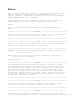
>>>>>>>>>>>>>>>>>>>>>>>>>>>>>>>>>>>>><<<<<<<<<<<<<<<<<<<<<<<<<<<<<<<<<<<<<< Serial Number The serial number is displayed on the bottom of the CPU next to the memory compartment cover.
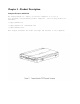
Chapter 1 - Product Description Computer Features and Models The Compaq Armada 1100 Family of Personal Computers is a line of full-featured, Pentium-based portable computers. The following models are available: o Compaq Armada 1110 o Compaq Armada 1120 and Armada 1125 o Compaq Armada 1120T This chapter describes the model offerings and features of the computers.
Models The Compaq Armada 1100 Family of Personal Computers is available in the models shown in Table 1-1. Table 1-1. Compaq Armada 1100 Family Models =========================================================================== Model Processor Display Hard Drive =========================================================================== Armada 1110 75-MHz Pentium 10.4-inch CSTN 810 MB --------------------------------------------------------------------------Armada 1120 100-MHz Pentium 10.
Security Features The computer has the following security features: o Ability to secure the computer to an immovable object with an optional cable lock. o Ability to establish power-on and setup passwords. o Ability to disable the following devices from the Security menu in Computer Setup: serial port, parallel port, PC Card slots, diskette drive, diskette drive boot ability.
AC Adapter The AC adapter supplies DC voltage to the system converter to operate and/or charge the installed battery pack. The adapter provides sufficient power to charge the battery pack in 1.5 hours or less with the system off, or in 3.5 hours or less with the system on. The AC adapter power specifications are presented in Chapter 7. Automobile Adapter The automobile adapter is used to charge the computer while traveling in an automobile. The Auto Adapter power specifications are presented in Chapter 7.
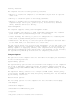
Rear Components The rear components are shown in the following figure and identified in this section: [1] Power connector [2] Parallel connector [3] Serial connector [4] Keyboard/mouse connector [5] External monitor connector
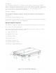
Bottom Components The bottom external components are shown in the following figure and are identified in this section: [1] Battery compartment [2] Memory compartment
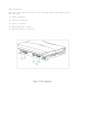
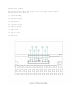
Status Panel Lights The status panel lights are shown in the following figure and are identified in this section: [1] Power/standby [2] Battery charge [3] Hard drive [4] Diskette drive [5] Battery gauge [6] Caps Lock [7] Scroll Lock [8] Num Lock
System Design This section provides an overview of the system design. System Board and Processor The OPTi-designed Viper-N Chipset provides PCI bus, ISA bus, cache controller, memory controller, and peripherals controller: o OPTi 82C557M System Controller o OPTi 82C556M Data Buffer Controller o OPTi 82C558E Integrated Peripherals Controller The computer supports a 75-MHz (P54C) CPU at 50-MHz bus speed, and a 100-MHz (P54LM) CPU at 66-MHz bus speed.
Computer Design Overview This section presents a brief design overview of the computer. See Chapter 3 for an overview of the system unit and the display assembly from the perspective of replacing components in the field. All replacement parts are listed in Chapter 3, and removal and replacement procedures are presented in Chapter 5. The computer is a traditional clam shell design with a display unit and a system unit. The computer opens to reveal a backlighted LCD display and a full-sized keyboard.
Chapter 2 - Troubleshooting Introduction This chapter contains troubleshooting information for the computer. The basic steps in troubleshooting include: 1. Completing the preliminary steps listed in Section 2.1. 2. Running the Power-On Self-Test (POST) as described in Section 2.4. 3. Running the Computer Checkup (TEST) as described in Section 2.5. 4. Performing the recommended actions described in the diagnostic tables in Section 2.
computer, the problem could be with the external device or its cable. Isolate the problem by running POST with and without the external device connected. 6. Use Advanced Diagnostics and loopback plugs in the serial and parallel connectors if you plan to test these ports. To run Advanced Diagnostics, complete the following steps: a. Insert the Diagnostics diskette into the diskette drive and turn on the computer. b. At the Welcome Screen, enter Ctrl+A. c. Press Enter to accept OK. d.
o Boot memory test o Keyboard numlock o Boot sequence o Boot display o Serial port settings o Parallel port settings o Power-on password o Diskette drive boot disable To run Computer Setup, complete the following steps: Computer Setup automatically recognizes and configures the system for new Compaq devices. It does this without prompting you for information about the devices.
o Power Management Enabled While on Battery o Conservation Level Medium o Low-Battery Warning Beeps Enabled o External Energy Saving Monitor Disabled >>>>>>>>>>>>>>>>>>>>>>>>>>>>>>>>> CAUTION <<<<<<<<<<<<<<<<<<<<<<<<<<<<<<<<< If you disable Power Management or Hibernation, you must take immediate action to resolve a low-battery condition to prevent losing unsaved information.
The next time you press F10 (after POST) to run Computer Setup, a password prompt appears on the screen. If you enter the password incorrectly, you are prompted to reenter the password. If you forget the setup password, you cannot change the system configuration until the computer memory is cleared of the password. Refer to Section 2.2 in this guide for procedures for clearing the password.
o PC Card slots o Diskette drive Disabling these devices prevents the unauthorized transfer of data using the devices. To reenable a device, deselect the Disable option and restart the computer. Exit Menu The Exit menu has four options: o Save and Exit: Saves configuration changes, but some changes do not take effect until the computer is restarted. o Exit (No Save): Exits and does not save the changes you have made.
Table 2-1. Warning Messages =========================================================================== Message Description =========================================================================== Clock not ticking correctly The real time clock is not ticking. --------------------------------------------------------------------------CMOS checksum invalid, run CMOS RAM information has been corrupted and SCU needs to be reinitialized by running Computer Setup.
Table 2-2. Fatal Error Messages =========================================================================== Message Description Beep Code =========================================================================== CMOS RAM test failed A walking bit test of CMOS RAM location 0E (Hex) - 3F (Hex) failed.
The following table lists some of the Fatal Error beep codes, along with the beep sequence (short, long, pause) and the meaning of the beeps. Table 2-3. Fatal Error Beep Codes =========================================================================== Beep Code Beep Sequence Explanation Remedy =========================================================================== 0 S-S-S-P-S-S-L-P The DMA page registers are faulty. Replace system board. 1 S-S-S-P-S-L-S-P The refresh circuitry is faulty.
Compaq Diagnostics Run the Compaq Diagnostics utilities diskette when you want to view or test system information and installed or connected devices. The Diagnostics menu includes the following utilities: o Computer Checkup (TEST) o View System Information (INSPECT) o Prepare Computer for a Compaq Service Call (RemotePaq) If you have a problem you cannot solve, run the Diagnostics utilities before you call for support.
9. Select one of the following from the Test Option menu: o Quick Check Diagnostics. Runs a quick, general test on each device with a minimal number of prompts. If errors occur, they display when the testing is complete. You cannot print or save the error messages. o Automatic Diagnostics. Runs unattended, maximum testing of each device with minimal prompts. You can choose how many times to run the tests, to stop on errors, or to print or save a log of errors. o Prompted Diagnostics.
RemotePaq This utility is only available in certain geographical areas and requires a modem. It allows a Compaq reseller or service provider to automatically run diagnostics on the computer. To run RemotePaq, follow these steps: 1. Insert the Compaq Diagnostics diskette into drive A. 2. Turn on or restart the computer. The computer starts from drive A, and the Diagnostics Welcome screen appears. 3. Press Enter to continue. The Diagnostics menu appears. 4.
113 - xx Protected mode test failed --------------------------------------------------------------------------114 - 01 Speaker test failed 1. Check system configuration. 2. Verify cable connections to speaker. 3. Replace the system board and retest. =========================================================================== Table 2-5.
Table 2-7. Parallel Printer Test Error Codes =========================================================================== Error Code Description Recommended Action =========================================================================== 401 - xx Printer failed or The following steps apply to error not connected codes 401 - xx through 403 - xx: 402 - xx Failed Port Test 1. Connect the printer. 2. Check power to the printer. 403 - xx Printer pattern test 3.
Table 2-9. Serial Test Error Codes =========================================================================== Error Code Description Recommended Action =========================================================================== 1101 - xx Serial port test 1. Check port configuration failed 2. Replace the system board and retest. =========================================================================== Table 2-10.
Table 2-11.
--------------------------------------------------------------------------Error Code Description Recommended Action --------------------------------------------------------------------------2402 - xx Video memory test The following steps apply to error failed codes 2402 - xx through 2456 - xx: 2403 - xx Video attribute test failed 2404 - xx Video character set test failed 2405 - xx Video 80 x 25 mode 9 x 14 character cell test failed 2406 - xx Video 80 x 25 mode 8 x 8 character cell test failed 2408
--------------------------------------------------------------------------Error Code Description Recommended Action --------------------------------------------------------------------------2419 - xx ECG/VGC ROM checksum The following steps apply to error test failed codes 2402 - xx through 2456 - xx: 2421 - xx ECG/VGC 640 x 200 graphics mode test failed 2422 - xx ECG/VGC 640 x 350 16 color set test failed 2423 - xx ECG/VGC 640 x 350 64 color set test failed 2431 - xx 640 x 480 graphics test failure
Table 2-12. Audio Test Error Codes =========================================================================== Error Code Description Recommended Action =========================================================================== 3206 - xx Audio System Replace the system board and retest. Internal Error =========================================================================== Table 2-13.
Solving Audio Problems Some common audio problems and solutions are listed in the following table. Table 2-14. Solving Audio Problems =========================================================================== Problem Probable Cause Solution(s) =========================================================================== Computer beeps once This is typical; it No action is required. after you turn it indicates successful on. completion of the Power-On Self-Test (POST).
Solving Battery and Battery Gauge Problems Some common causes and solutions for battery problems are listed in the following table. The "Solving Power Problems" section in this chapter also may be applicable. Table 2-15. Solving Battery and Battery Gauge Problems =========================================================================== Problem Probable Cause Solution(s) =========================================================================== Computer won't turn Battery is discharged.
--------------------------------------------------------------------------Problem Probable Cause Solution(s) --------------------------------------------------------------------------Battery light Battery pack is already No action is necessary. doesn't light and charged. battery pack won't fast charge. Battery pack was exposed to temperature extremes. Allow time for the battery pack to return to room temperature. Battery pack is at end Replace battery pack. of its life.
--------------------------------------------------------------------------Battery pack Power management is Enable power management operating time is turned off or disabled. in Computer Setup and in far less than the Windows Power Properties. documented The power management icon average operating should be visible on the time. status panel. An external device or PC Card is draining the battery. Turn off or disconnect external devices when not using them. Battery pack has partially selfdischarged.
Solving Diskette and Diskette Drive Problems Some common causes and solutions for diskette and diskette drive problems are listed in the following table. Table 2-16. Solving Diskette and Diskette Drive Problems =========================================================================== Problem Probable Cause Solution(s) =========================================================================== Diskette drive icon Diskette drive is not Remove the diskette drive does not turn on. installed properly.
Solving Hard Drive Problems Some common causes and solutions for hard drive problems are listed in the following table. >>>>>>>>>>>>>>>>>>>>>>>>>>>>>>>>> CAUTION <<<<<<<<<<<<<<<<<<<<<<<<<<<<<<<<< To prevent loss of information, always maintain an up-to- date backup of your hard drive at all times, in case of errors or failures. >>>>>>>>>>>>>>>>>>>>>>>>>>>>>>>>>>>>><<<<<<<<<<<<<<<<<<<<<<<<<<<<<<<<<<<<<< Table 2-17.
Solving Keyboard/Numeric Keypad Problems Some common causes and solutions for keyboard/numeric keypad problems are listed in the following table. Table 2-19. Solving Keyboard/Numeric Keypad Problems =========================================================================== Problem Probable Cause Solution(s) =========================================================================== Embedded numeric Num Lock function is not Press the Fn+NumLk keys keypad on computer enabled.
Solving Memory Problems Some common causes and solutions for memory problems are listed in the following table. Table 2-21. Solving Memory Problems =========================================================================== Problem Probable Cause Solution(s) =========================================================================== Memory count during Optional memory Ensure that the optional Power-On Self-Test expansion card is memory expansion card is (POST) is incorrect.
Solving PC Card Problems Some common causes and solutions for PC Card problems are listed in the following table. Table 2-22. Solving PC Card Problems =========================================================================== Problem Probable Cause Solution(s) =========================================================================== PC Card error The PC Card slot is Run Computer Setup and messages appear when disabled. enable the PC Card slots the computer is on the Security Menu. turned on.
--------------------------------------------------------------------------PC Card modem, fax, Card is not fully Ensure the card is or network card inserted into the slot inserted in the correct does not work. or is not inserted orientation. properly. Telephone cord is not plugged in all the way. Check and secure telephone connection. Necessary drivers are Install drivers. not installed (turned on).
Solving Power Problems Also see "Solving Battery and Battery Gauge Problems" in this chapter. Table 2-23. Solving Power Problems =========================================================================== Problem Probable Cause Solution(s) =========================================================================== Computer won't turn Computer is not Insert battery or connect on and battery pack connected to a power an external power source. is not inserted. source.
Measuring Power Signals The following power signals can be measured on the top side of the PCA. =========================================================================== VDD (+5V) Across Tantalum CAPs C574, C573 --------------------------------------------------------------------------+3.3V Across Tantalum CAPs C578, C575 --------------------------------------------------------------------------VCPU (3.3V on -001 and 2.
Printer prints garbled information. Correct printer drivers are not installed. Refer to the printer documentation to Install the correct printer driver. Cable is not connected properly. Ensure that the printer signal cable is properly connected to the computer. Cable is defective. Replace the printer cable and retest.
Table 2-25. Solving Screen Problems =========================================================================== Problem Probable Cause Solution(s) =========================================================================== Characters are dim. The brightness or Adjust the control(s) on contrast (if applicable) the right side of the control is not set computer display. properly. Computer screen is in Tilt the display or move direct light. computer.
Solving Software Application Problems Most software application or installation problems occur as a result of one or more of the following: o The application was not installed correctly. o The CONFIG.SYS file was not configured correctly. o Memory was not allocated correctly. o The AUTOEXEC.BAT file was not edited correctly. o A conflict exists between applications. Table 2-26.
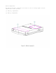
Chapter 3 - Illustrated Parts Introduction This chapter provides an illustrated parts breakdown and a reference for spare part numbers for the Compaq Armada 1100 Family of Personal Computers. The computer combines a display assembly and system unit module. The display and system unit module are joined together by clutches on either side, which are secured by screws in the chassis and display enclosure, and which allow the display to open and close.
System Unit Module Overview The system unit module (Figure 3-2) contains the following major components: o Hard drive - The hard drive mounts to the system chassis with a hard drive bracket and connects directly to the system board with no intervening cables. The hard drive bracket attaches to the hard drive with four screws. The drive is protected by an insulator between the system board and the drive. o Memory expansion board - System memory can be upgraded with an optional memory expansion board.
Display Assembly Overview All display assemblies (Figure 3-3) include the following replaceable parts: o Bezel o Enclosure latches o Liquid crystal display (LCD) panel o Shield o Enclosure o Display cable o Display ground cable o Inverter board o Clutches The display cable is a prefolded, flex cable that connects to the display inverter board with a low insertion force (LIF) connector.
The display ground cable connects to the display shield on one end, and the other end clips to the flex ground bracket located above the serial port between the system board and system chassis. The display inverter board is aligned to the right of the display enclosure with pins. One end connects to the display cable; the other end connects to the backlight cable of the LCD panel. To replace the display assembly, the assembly must be removed from the system unit module.
System Unit Module Parts Table 3-1. System Unit Module =========================================================================== Description Spare Part Number Notes =========================================================================== 1. Base enclosure 262492-001 Includes: a. PC Card eject levers and pin b. bottom PC Card door and spring c. battery latch button and spring d. handle bracket, screws, and washers e. battery shield, insulator f. tilt foot and screws g. battery clip h.
2. System board - with 75 MHz processor Includes: a. heatspreader plate 262406-001 b. diskette drive and hard drive insulators * - with 100 MHz c. EMI gasket * processor 262407-001 d. heatspreader clip * e. heatspreader screws * --------------------------------------------------------------------------3. Diskette drive bracket 189240-001 --------------------------------------------------------------------------4. Diskette drive 147963-001 Includes: a. label * b. battery clip, spring, spacer assembly * c.
Color STN (10.4 in) Display Assembly Parts Table 3-2. CSTN (10.4 in) Display Assembly =========================================================================== Spare Part Description Number Notes =========================================================================== 1. Display bezel 189246-001 --------------------------------------------------------------------------2.
6. Display enclosure 189245-001 Includes: left and right latches, springs, left and right display clutches logos (for Armada 1100 and Contura 400), pad for Sharp CSTN (for use with Contura 400 CSTN), and bezel screws * --------------------------------------------------------------------------7. Screw kit * 147885-001 (See Table 3-12 for contents and where used matrix.
Table 3-3. CTFT (10.4 in) Display Assembly =========================================================================== Spare Part Description Number Notes =========================================================================== 1. Display bezel 189244-001 --------------------------------------------------------------------------2. Backlight inverter Includes Caution, High board 189136-001 Voltage label * --------------------------------------------------------------------------3.
Keyboards Table 3-4. Armada 1100 Notebook Keyboards =========================================================================== Description All Models =========================================================================== 1. CPU cover includes: 147860-001 a. PC Card door b. light deflector c. spring * --------------------------------------------------------------------------2. U.S. 147875-001 --------------------------------------------------------------------------3. U.K.
10. Swedish/Finnish 147875-010 * --------------------------------------------------------------------------11. Swiss 147875-011 * --------------------------------------------------------------------------12. French Canadian 147875-012 * --------------------------------------------------------------------------13. Portuguese 147875-013 * --------------------------------------------------------------------------14.
3. Enhanced III - German 140536-104 * 4. Enhanced III - French 140536-105 * 5. Enhanced III - Italian 140536-106 * 6. Enhanced III - Spanish 140536-107 * 7. Enhanced III - Danish 140536-108 * 8. Enhanced III - Norwegian 140536-109 * 9. Enhanced III - Swedish/Finnish 140536-110 * 10. Enhanced III - Swiss 140536-111 * 11. Enhanced III - French Canadian 140536-112 * 12. Enhanced III - Portuguese 140536-113 * 13. Enhanced III - Turkish 140536-114 * 14.
Cables Table 3-6. Cables =========================================================================== Description Spare Part Number =========================================================================== 1. Display cables a. CTFT display cable 189247-001 b. CSTN display cable 189247-001, 262494-001 c. XOVER board for CSTN 189247-001, 262494-001 d. Ground cable 189247-001, 262494-001 --------------------------------------------------------------------------2.
AC Adapter and Power Cord Table 3-7. AC Adapter and Power Cord =========================================================================== Description Spare Part Numbers =========================================================================== 1. AC adapter 147679-002 2. Power cord (U.S./Canada) 197230-001 3. Power cord (U.K.) 197232-001 * 4. Power cord (Europe) 197231-001 * 5. Power cord (Japan) 197233-001 * 6. Power cord (Australia) 197234-001 * 7.
Memory Expansion Boards Table 3-8. Memory Boards =========================================================================== Description Spare Part Numbers =========================================================================== Memory expansion boards 1. 8 MB 220584-001 2.
Slipcase Table 3-9. Slipcase =========================================================================== Description Spare Part Number =========================================================================== Slipcase 194162-001 =========================================================================== Automobile Adapter Table 3-10.
Miscellaneous CPU Kits Table 3-11.
Computer Miscellaneous Screws Kit Table 3-12a. Computer Miscellaneous Screws Kit Contents and Use =========================================================================== Description Spare Part Number =========================================================================== Screws and Fasteners Kit 147885-001 =========================================================================== Table 3-12b.
Description: M2.5 x 5.0 Type: Where Used: Trackball assembly to base Drive: SL/T8 Quantity Required: 2 --------------------------------------------------------------------------Description: M2.5 x 5.0 Type: Where Used: Hard drive bracket to system chassis Drive: T8 Quantity Required: 1 --------------------------------------------------------------------------Description: M2.5 x 4.
Documentation Table 3-13.
Chapter 4 - Removal and Replacement Preliminaries Introduction This chapter provides general service information for the Compaq Armada 1100 Family of Personal Computers. Adherence to the procedures and precautions described in this chapter is essential for proper service. Electrostatic Discharge A sudden discharge of static electricity from a finger or other conductor can destroy static-sensitive devices or microcircuitry. Often the spark is neither felt or heard, but damage occurs.
Preventing Electrostatic Damage to Equipment Many electronic components are sensitive to ESD. Circuitry design and structure determine the degree of sensitivity. The following proper packaging and grounding precautions are necessary to prevent damage: o Protect all electrostatic parts and assemblies with conductive or approved containers or packaging. o Keep electrostatic-sensitive parts in their containers until they arrive at static-free stations.
Grounding Workstations To prevent static damage at the workstation, use the following precautions: o Cover the workstation with approved static-dissipative material. Provide a wrist strap connected to the work surface and properly grounded tools and equipment. o Use static-dissipative mats, heel straps, or air ionizers to give added protection. o Handle electrostatic sensitive components, parts, and assemblies by the case or PCB laminate. Handle them only at static-free workstations.
o Conductive table-top workstations with ground cord of 1 megohm of resistance o Static dissipative table or floor mats with hard tie to ground o Field service kits o Static awareness labels o Wrist straps and footwear straps providing 1 megohm +/- 10% resistance o Material handling packages o Conductive plastic bags o Conductive plastic tubes o Conductive tote boxes o Metal tote boxes o Opaque shielding bags o Transparent metallized shielding bags o Transparent shielding tubes Service Considerations Liste
Chapter 5 - Computer Removal and Replacement Procedures Introduction This chapter provides complete removal and replacement procedures for the computer. Serial Number The computer serial number should be reported to Compaq when requesting information or ordering spare parts. The serial number is displayed on the bottom of the CPU, next to the memory compartment cover [1].
5.4 5.5 5.6 5.7 5.8 5.9 5.10 5.11 5.12 5.13 5.14 5.15 5.16 5.17 5.18 5.19 5.20 5.21 5.22 5.
Preparing the Computer >>>>>>>>>>>>>>>>>>>>>>>>>>>>>>>>> WARNING <<<<<<<<<<<<<<<<<<<<<<<<<<<<<<<<< Ensure that the power cord is disconnected from the electrical outlet and that the battery pack is removed from the computer before beginning replacement procedures. Failure to disconnect power could result in serious injury or damage to the equipment.
5. Disconnect the AC Adapter power cord from the computer (Figure 5-3). 6. Eject the diskette (Figure 5-3). 7. Open the battery compartment by lifting up the front of the computer [1] and sliding the battery compartment release button to the right [2]. The battery compartment opens slightly. Lower the compartment [3] (Figure 5-4).
8. Remove the battery pack (Figure 5-5).
>>>>>>>>>>>>>>>>>>>>>>>>>>>>>>>>> CAUTION <<<<<<<<<<<<<<<<<<<<<<<<<<<<<<<<< Metal objects can damage the battery pack and the connectors inside the compartment. To prevent damage, do not let metal objects touch any of the connectors. Do not place any objects other than the battery pack in the battery compartment. >>>>>>>>>>>>>>>>>>>>>>>>>>>>>>>>>>>>><<<<<<<<<<<<<<<<<<<<<<<<<<<<<<<<<<<<<< 9. Close the empty battery compartment.
Handle Bracket This procedure is necessary if replacing the handle bracket or if separating the display assembly from the system unit module. Removing the Handle Bracket To remove the handle bracket, follow these steps: 1. Turn the computer off and remove all external devices, including the battery pack and the AC Adapter. Remove the diskette and PC Card, if installed (Section 5.3). 2. Close the computer and turn it topside down. 3.
6. To install the handle bracket, reverse the previous steps. Discard the old screws and replace with new screws. Tilt Feet This procedure is necessary if replacing the tilt feet or if separating the display assembly from the system unit module. Removing the Tilt Feet To remove the tilt feet, follow these steps: 1. Turn the computer off and remove all external devices, including the battery pack and the AC Adapter. Remove the diskette and PC Card, if installed (Section 5.3). 2.
4. To install the tilt foot, reverse the previous steps. Discard the old screws and replace with new screws. Memory Expansion Board This section contains removal and replacement procedures for the memory compartment cover and the memory expansion board. The memory compartment cover and the bottom of the CPU base are embossed with arrows and two icons that indicate whether the memory compartment cover is unlocked [1] or locked [2] (Figure 5-10).
Removing and Replacing the Memory Compartment Cover To remove the memory compartment cover, follow these steps: 1. Turn the computer off and remove all external devices, including the battery pack and the AC Adapter. Remove the diskette and PC Card, if installed (Section 5.3). 2. Close the computer and turn it topside down. 3. Slide the memory compartment cover toward the rear of the computer and lift up (Figure 5-11).
4. To replace the memory compartment cover, reverse the previous steps. Removing the Memory Expansion Board To remove the memory expansion board, follow these steps: 1. Remove the memory compartment cover. Refer to "Removing and Replacing the Memory Compartment Cover" in this section. 2. Press in on one of the small tabs holding the board in place [1], let the board pop up, then pull it slightly up and out [2] (Figure 5-12).
3. Replace the memory compartment cover. Refer to "Removing and Replacing the Memory Compartment Cover" in this section. Keyboard Assembly This section contains removal and replacement procedures for the following keyboard assembly components: o CPU cover o Keyboard o Top PC Card door and spring NOTE: The bottom PC Card door and spring are part of the CPU base. Removing the Keyboard Assembly To remove the keyboard assembly, follow these steps: 1.
>>>>>>>>>>>>>>>>>>>>>>>>>>>>>>>>>>>>><<<<<<<<<<<<<<<<<<<<<<<<<<<<<<<<<<<<<< 3. Remove the seven screws from the bottom of the computer (Figure 5-14). 4. Carefully turn the computer topside up and open the display to its fully opened position (135-degree angle) (Figure 5-15).
5. Using the case utility tool, lift up the outside rear corners of the keyboard assembly to release the keyboard snaps [1], and tilt the keyboard assembly toward you to release the keyboard connector [2] (Figure 5-16). IMPORTANT: When using the case utility tool, use care to keep it out of the diskette drive area. >>>>>>>>>>>>>>>>>>>>>>>>>>>>>>>>> CAUTION <<<<<<<<<<<<<<<<<<<<<<<<<<<<<<<<< The computer becomes top-heavy when the keyboard assembly is removed and the display is opened.
6 6. Remove the keyboard assembly by lifting it up [1] and off the front of the computer [2] (Figure 5-17). 7. Position the display to a 90-degree angle (Figure 5-18).
Removing the CPU Cover To remove the CPU cover for replacement, follow these steps. 1. Remove the keyboard assembly from the computer. Refer to "Removing the Keyboard Assembly" in this section. 2. Turn the keyboard assembly topside down. >>>>>>>>>>>>>>>>>>>>>>>>>>>>>>>>> CAUTION <<<<<<<<<<<<<<<<<<<<<<<<<<<<<<<<< Note the position of the screws removed from the bottom of the keyboard assembly. The remaining screws holes are for the screws that go through the keyboard assembly to the CPU base.
5. To replace the CPU cover, reverse the previous steps. IMPORTANT: A set of warning labels can be ordered as a spare parts kit (spare part number 189288-001). Install the label in the upper right-corner of the cover. This label contains a warning message to prevent physical discomfort and harm. Installation of this label is essential. Removing the Top PC Card (PCMCIA) Door and Spring To remove the top PC Card door and spring from the keyboard assembly, follow these steps: 1.
Replacing the Top PC Card (PCMCIA) Door and Spring To replace the top PC Card door and spring to the keyboard assembly, follow these steps: 1. Install the PC Card spring on the door post, ensuring that the bent arm of the spring is placed against the rib on the PC Card door (Figure 5-21).
2. Install the PC Card door, ensuring that the spring is placed between the post [1] and the rib [2] (Figure 5-22). Replacing the Keyboard Assembly To install a new keyboard assembly or replace the existing keyboard assembly in the computer, follow these steps: 1. Open the display to its fully opened position of 135-degrees (Figure 5-23).
2. Angle the front end of the keyboard assembly into place at the front edge of the system unit module. 3. Ensure that the front plastic seams of the keyboard assembly and the front of the system unit module are aligned and flush with each other. 4. Carefully lower the rear of the keyboard assembly to the system unit module and press the outside rear corners until the keyboard assembly snaps into place. 5. Verify the alignment of the keyboard assembly to the computer base.
Battery Compartment Components This section contains removal procedures for the following battery compartment components: o Battery compartment o Anti-skid pad o Battery release button spring o Battery release button Removing the Battery Compartment To remove the battery compartment components, follow these steps: 1. Turn the computer off and remove all external devices, including the battery pack and the AC Adapter. Remove the diskette and PC Card, if installed (Section 5.3). 2.
4. To replace the battery compartment, reverse the previous steps. Attaching the Anti-Skid Pads If installing a new battery compartment, two anti-skid pads must be attached to the bottom of the battery compartment. To attach the anti-skid pads, follow these steps: 1. Peel off the top layer of one of the anti-skid pads to expose the adhesive. 2. With the adhesive-side down, place the anti-skid pad into the raised oval outline on the battery compartment (Figure 5-26).
Removing the Battery Release Spring and Button To remove the battery release spring and button, follow these steps: 1. Turn the computer off and remove all external devices, including the battery pack and the AC Adapter. Remove the diskette and PC Card, if installed (Section 5.3). >>>>>>>>>>>>>>>>>>>>>>>>>>>>>>>>> CAUTION <<<<<<<<<<<<<<<<<<<<<<<<<<<<<<<<< The computer becomes top-heavy when the keyboard assembly is removed and the display is opened.
4. Rotate the battery release button counterclockwise, until it bows slightly, and lift it up to clear the hook on the computer base (Figure 5-28). 5. To replace the battery release button and spring, reverse the previous steps. Hard Drive This section contains removal procedures for the following hard drive components: o Hard drive o Hard drive bracket Removing the Hard Drive To remove the hard drive, follow these steps: 1.
4. Grasp the hard drive bracket and slide it toward the front of the computer to disconnect the hard drive from the system board . Then lift it up and out of the system chassis (Figure 5-30).
Removing the Hard Drive Bracket 1. Remove the keyboard assembly (Section 5.7). 2. Remove the hard drive and bracket. Refer to "Removing the Hard Drive" in this section. 3. Remove the four screws from the sides of the hard drive bracket and separate the bracket from the hard drive (Figure 5-31). 4. To replace the hard drive bracket, reverse the previous steps. For proper alignment, replace the rear screws first. Replacing the Hard Drive To replace the hard drive, follow these steps: 1.
2. Replace the screw that connects the hard drive and bracket to the system chassis (Figure 5-33).
Real-Time Clock Battery To remove the real-time clock battery, follow these steps: 1. Turn the computer off and remove all external devices, including the battery pack and the AC Adapter. Remove the diskette and PC Card, if installed (Section 5.3). >>>>>>>>>>>>>>>>>>>>>>>>>>>>>>>>> CAUTION <<<<<<<<<<<<<<<<<<<<<<<<<<<<<<<<< The computer becomes top-heavy when the keyboard assembly is removed and the display is opened.
>>>>>>>>>>>>>>>>>>>>>>>>>>>>>>>>> CAUTION <<<<<<<<<<<<<<<<<<<<<<<<<<<<<<<<< Do not touch the bottom of the battery during replacement. >>>>>>>>>>>>>>>>>>>>>>>>>>>>>>>>>>>>><<<<<<<<<<<<<<<<<<<<<<<<<<<<<<<<<<<<<< 4. To replace the real-time clock battery, reverse the previous steps. Integrated Optical Trackball Assembly To remove the integrated optical trackball assembly, follow these steps: 1. Turn the computer off and remove all external devices, including the battery pack and the AC Adapter.
4. Disconnect the integrated optical trackball assembly from the system board by pulling upward on the trackball assembly (Figure 5-36). 5. To replace the integrated optical trackball assembly, reverse the previous steps. Trackball Cleaning Procedures 1. Turn off the computer, disconnect AC power, and remove the battery pack. 2. Remove the optical trackball. 3. Remove any large particles of debris that have fallen into the trackball housing. 4.
7. Replace the battery pack and reconnect the AC power. Diskette Drive This section contains removal and replacement procedures for the following diskette drive components: o Diskette drive o Diskette drive bracket Removing the Diskette Drive To remove the diskette drive, follow these steps: 1. Turn the computer off and remove all external devices, including the battery pack and the AC Adapter. Remove the diskette and PC Card, if installed (Section 5.3).
>>>>>>>>>>>>>>>>>>>>>>>>>>>>>>>>> CAUTION <<<<<<<<<<<<<<<<<<<<<<<<<<<<<<<<< Screws in the computer are not interchangeable. As you remove screws, place them with the components you removed. Damage may occur if you insert the screws in the wrong place. >>>>>>>>>>>>>>>>>>>>>>>>>>>>>>>>>>>>><<<<<<<<<<<<<<<<<<<<<<<<<<<<<<<<<<<<<< 4. Remove the three screws that attach the diskette drive bracket to the system board, and the two screws that connect the bracket to the heatspreader (Figure 5-38).
Removing the Diskette Drive from the Diskette Drive Bracket 1. Remove the diskette drive from the system chassis. Refer to "Removing the Diskette Drive" in this section. 2. Remove the diskette drive from the bracket by removing the four screws from both sides of the bracket (Figure 5-40).
3. Separate the diskette drive from the bracket (Figure 5-41). 4. To replace the diskette drive into the bracket, reverse the previous steps. Replacing the Diskette Drive To replace the diskette drive into the system chassis, follow these steps: >>>>>>>>>>>>>>>>>>>>>>>>>>>>>>>>> CAUTION <<<<<<<<<<<<<<<<<<<<<<<<<<<<<<<<< When removing or replacing the diskette drive, hold it by grasping the vertical sides.
1 Replace the diskette drive into the diskette drive bracket. bracket Use the four 1. screws to secure the diskette drive to the bracket. NOTE: When replacing the diskette drive into the bracket, secure the front two screws first. 2. Toe in the back end of the diskette drive into the system chassis. IMPORTANT: Ensure that the diskette drive door does not catch on the outside edge of the system unit module. 3.
installed (Section 5.3). 2. Remove the memory expansion board, if installed (Section 5.6). 3. On the rear of the computer, use a 3/16 hex socket wrench to remove the six screw locks (Figure 5-43). >>>>>>>>>>>>>>>>>>>>>>>>>>>>>>>>> CAUTION <<<<<<<<<<<<<<<<<<<<<<<<<<<<<<<<< The computer becomes top-heavy when the keyboard assembly is removed and the display is opened. To prevent damage to the display and the computer, ensure that the display assembly is opened at a 90-degree angle.
twist the cable itself while it is seated in the ZIF connector. >>>>>>>>>>>>>>>>>>>>>>>>>>>>>>>>>>>>><<<<<<<<<<<<<<<<<<<<<<<<<<<<<<<<<<<<<< 8. Disconnect the display cable from the system board by pulling up both ends of the ZIF connector slide simultaneously [1], carefully opening the slide [2] (Figure 5-44). 9. Lift the display cable out of the connector slide [3], being careful not to pull or twist the cable (Figure 5-44). 10.
11. Remove the two keyboard ground clips from the chassis (Figure 5-46). 12. Remove the left clutch ground clip from the system chassis (Figure 5-47).
13. Remove the five screws from the system board and the two screws from the battery contact (Figure 5-48).
14. From the front of the computer, tilt the system board up, then lift the system board out of the system chassis (Figure 5-49). At this time, remove the PCMCIA rails from the system board if you have not ordered or acquired a replacement set of rails for the new system board you are about to install. If you need to remove the rail set, refer to "Removing the PC Card (PCMCIA) Rails" in Section 5.14. 15.
16. To replace the system board, reverse the previous steps. >>>>>>>>>>>>>>>>>>>>>>>>>>>>>>>>> CAUTION <<<<<<<<<<<<<<<<<<<<<<<<<<<<<<<<< When returning a system board for repair or when replacing a board, be careful that the contacts on the EMI clip do not become bent or otherwise damaged.
IMPORTANT: When replacing the system board, the screws must be replaced as follows: 1. Install screws [1] and [2] on the system board before replacing the remaining system board and battery contact screws (Figure 5-52). PC Card (PCMCIA) Assembly The PC Card assembly consists of the PC Card clip and PC Card rails. To remove the PC Card assembly or to remove part of the assembly, follow the steps below. Removing the PC Card Clip To remove the PC Card clip, follow these steps: 1.
2. Remove the keyboard assembly (Section 5.7). 3. Remove the system board (Section 5.13). 4. Remove the two screws of the PC Card rails from the bottom of the system board (Figure 5-53). 5. Remove the clip from the top of the PC Card (PCMCIA) header (Figure 5-53). 6. To replace the PC Card clip, reverse the previous steps. >>>>>>>>>>>>>>>>>>>>>>>>>>>>>>>>> CAUTION <<<<<<<<<<<<<<<<<<<<<<<<<<<<<<<<< Do not over tighten the clip, or it can become damaged.
1. Remove the PC Card clip. Refer to "Removing the PC Card Clip" in this section. 2. Using the connector removal tool, compress the set of clips on the right and left sides of the rails. This allows the rails to be shifted right or left for removal. 3. Slide the rails out of the header (Figure 5-54). 4. To replace the PC Card rails, reverse the previous steps. The PC Card rails go under the edge of the header.
installed (Section 5.3). 2. Remove the keyboard assembly (Section 5.7). 3. Remove the PC Card ejection lever pin from the system chassis (Figure 5-55). 4. Remove the top PC Card ejection lever (Figure 5-56).
5. Remove the bottom PC Card ejection lever from the boss on the CPU base Figure 5-57). 6. To replace the PC Card ejection levers and pin, reverse the previous steps. PC Card (PCMCIA) Doors and Springs This section contains removal and replacement procedures for the PC Card doors and springs. The top PC Card door and spring are located on the keyboard assembly and the bottom PC Card door and spring are located on the CPU base.
To remove the top PC Card door and spring, follow these steps: 1. Turn the computer off and remove all external devices, including the battery pack and the AC Adapter. Remove the diskette and PC Card, if installed (Section 5.3). >>>>>>>>>>>>>>>>>>>>>>>>>>>>>>>>> CAUTION <<<<<<<<<<<<<<<<<<<<<<<<<<<<<<<<< The computer becomes top-heavy when the keyboard assembly is removed and the display is opened.
2. Install the PC Card door, making sure the spring is placed between the notch [1] and the rib [2] (Figure 5-60).
Bottom PC Card (PCMCIA) Door and Spring The bottom PC Card door and spring are located on the CPU base. To remove the bottom PC Card door and spring, follow these steps: 1. Turn the computer off and remove all external devices, including the battery pack and the AC Adapter. Remove the diskette and PC Card, if installed (Section 5.3). >>>>>>>>>>>>>>>>>>>>>>>>>>>>>>>>> CAUTION <<<<<<<<<<<<<<<<<<<<<<<<<<<<<<<<< The computer becomes top-heavy when the keyboard assembly is removed and the display is opened.
To replace the bottom PC Card spring and door, follow these steps: 1. Install the PC Card spring on the door post, making sure the bent arm of the spring is placed against the rib on the PC Card door (Figure 5-62). 2. Install the PC Card door, making sure the spring is placed between the notch [1] and the rib [2] (Figure 5-63).
System Chassis To remove the system chassis, follow these steps: 1. Turn the computer off and remove all external devices, including the battery pack and the AC Adapter. Remove the diskette and PC Card, if installed (Section 5.3). 2. Remove the handle bracket on either side of the computer (Section 5.4). 3. Remove the tilt feet on either side of the computer (Section 5.5).
8. Remove the display assembly from the system unit module (Figure 5-65). 9. Slide the trough at the rear of the CPU base to the right, then lift up to remove (Figure 5-66).
10. Remove the PC Card ejection levers and pin (Section 5.15). 11. Remove the system chassis by gently separating it from the CPU base and lifting out the system chassis (Figure 5-67).
12. To replace the system chassis, reverse the previous steps, being sure to achieve proper alignment by fitting the two slots in the chassis over the two small steps on the CPU base. CPU Base This section provides removal and replacement procedures for the following CPU base components: o Battery shield clip o Lock provision plate o Anti-skid pads Removing and Replacing the Battery Shield Clip To remove the battery shield clip, follow these steps: 1.
5. To replace the battery shield clip, reverse the previous steps. Removing and Replacing the Lock Provision Plate To remove the lock provision plate, follow these steps: 1. Turn the computer off and remove all external devices, including the battery pack and the AC Adapter. Remove the diskette and PC Card, if installed (Section 5.3). >>>>>>>>>>>>>>>>>>>>>>>>>>>>>>>>> CAUTION <<<<<<<<<<<<<<<<<<<<<<<<<<<<<<<<< The computer becomes top-heavy when the keyboard assembly is removed and the display is opened.
4. To replace the lock provision plate, reverse the previous steps. Attaching the Anti-Skid Pads If replacing the CPU base, two anti-skid pads for the battery tray and the two for the CPU base must be attached to the bottom of the base. To attach the anti-skid pads, follow these steps: 1. Peel off the top layer of one of the anti-skid pads to expose the adhesive. 2. With the adhesive side down, place the anti-skid pad into the raised oval outline on the CPU base and the battery tray (Figure 5-70).
o Bezel o Latches o Inverter board Removing and Replacing the Display Bezel To remove the display bezel, follow these steps: 1. Turn the computer off and remove all external devices, including the battery pack and the AC Adapter. Remove the diskette and PC Card, if installed (Section 5.3). 2. Open the computer. 3. Remove the four screws from the display bezel (Figure 5-71). 4. Tilt the display to approximately a 110-degree angle. 5.
6. To replace the bezel, reverse the previous steps. >>>>>>>>>>>>>>>>>>>>>>>>>>>>>>>>> CAUTION <<<<<<<<<<<<<<<<<<<<<<<<<<<<<<<<< The unit can become top-heavy when pressure is applied while replacing the bezel. Supporting the unit with your hands will prevent it from falling over.
6. Remove the display latch spring from the latch (Figure 5-74).
Replacing the Display Enclosure Springs and Latches To replace the display springs and latches, follow these steps: 1. Hook the display latch spring on to the display latch [1] and place the display latch spring over the post in the display enclosure [2] (Figure 5-75). 2. Slide the display latch into place on either side of the display enclosure (Figure 5-76).
Removing the Display Inverter Board from the CSTN (10.4 in) Display >>>>>>>>>>>>>>>>>>>>>>>>>>>>>>>>> WARNING <<<<<<<<<<<<<<<<<<<<<<<<<<<<<<<<< Ensure that the power cord is disconnected from the electrical outlet and that the battery pack is removed from the computer before beginning replacement procedures. Failure to disconnect power could result in serious injury or damage to the equipment.
>>>>>>>>>>>>>>>>>>>>>>>>>>>>>>>>> WARNING <<<<<<<<<<<<<<<<<<<<<<<<<<<<<<<<< Ensure that the power cord is disconnected from the electrical outlet and that the battery pack is removed from the computer before beginning replacement procedures. Failure to disconnect power could result in serious injury or damage to the equipment. >>>>>>>>>>>>>>>>>>>>>>>>>>>>>>>>>>>>><<<<<<<<<<<<<<<<<<<<<<<<<<<<<<<<<<<<<< 5.
Removing the Display Inverter Board from the CTFT (10.4 in) Display >>>>>>>>>>>>>>>>>>>>>>>>>>>>>>>>> WARNING <<<<<<<<<<<<<<<<<<<<<<<<<<<<<<<<< Ensure that the power cord is disconnected from the electrical outlet and that the battery pack is removed from the computer before beginning replacement procedures. Failure to disconnect power could result in serious injury or damage to the equipment.
To remove the inverter board for the CTFT (10.4 in) Display, follow these steps: 1. Turn the computer off and remove all external devices, including the battery pack and the AC Adapter. Remove the diskette and PC Card, if installed (Section 5.3). 2. Open the computer. 3. Remove the display bezel. Refer to "Removing and Replacing the Display Bezel" in this section.
h h b k i d f h computer b f b i i that the battery pack is removed from the before beginning replacement procedures. Failure to disconnect power could result in serious injury or damage to the equipment. >>>>>>>>>>>>>>>>>>>>>>>>>>>>>>>>>>>>><<<<<<<<<<<<<<<<<<<<<<<<<<<<<<<<<<<<<< 5. Unplug the backlight cable [1] from the display inverter board to free the inverter board from the display enclosure (Figure 5-81). 6.
These steps must be followed whenever replacing any component in the display assembly because of high susceptibility to electrostatic discharge, which will damage the LCD panel. >>>>>>>>>>>>>>>>>>>>>>>>>>>>>>>>>>>>><<<<<<<<<<<<<<<<<<<<<<<<<<<<<<<<<<<<<< >>>>>>>>>>>>>>>>>>>>>>>>>>>>>>>>> CAUTION <<<<<<<<<<<<<<<<<<<<<<<<<<<<<<<<< When servicing the computer, ensure that cables are placed in their proper location to avoid pinching during the reassembly process.
The ZIF connector and its attached cable can be damaged easily. Handle only the connector slide when disconnecting the ZIF connector. Never pull or twist the cable itself while it is seated in the ZIF connector. >>>>>>>>>>>>>>>>>>>>>>>>>>>>>>>>>>>>><<<<<<<<<<<<<<<<<<<<<<<<<<<<<<<<<<<<<< 4. Remove the display cable from the system board by pulling up both ends of the ZIF connector slide simultaneously [1], carefully opening the slide [2] (Figure 5-82). 5.
>>>>>>>>>>>>>>>>>>>>>>>>>>>>>>>>> CAUTION <<<<<<<<<<<<<<<<<<<<<<<<<<<<<<<<< To prevent damage to the trough, ensure that the trough does not tilt forward into the CPU base when the bezel is removed. >>>>>>>>>>>>>>>>>>>>>>>>>>>>>>>>>>>>><<<<<<<<<<<<<<<<<<<<<<<<<<<<<<<<<<<<<< 7. Remove the display bezel (Section 5.19). 8. Remove the inverter board (Section 5.19). 9. Remove the display cable and backlight cable from the inverter board (Section 5.19).
>>>>>>>>>>>>>>>>>>>>>>>>>>>>>>>>> CAUTION <<<<<<<<<<<<<<<<<<<<<<<<<<<<<<<<< When servicing the computer, ensure that cables are placed in their proper location to avoid pinching during the reassembly process. Improper cable placement can cause severe damage to the unit. >>>>>>>>>>>>>>>>>>>>>>>>>>>>>>>>>>>>><<<<<<<<<<<<<<<<<<<<<<<<<<<<<<<<<<<<<< 11. Remove the screws that secure the CSTN (10.4 in) panel and shield to the display enclosure (Figure 5-85).
12. Carefully remove the CSTN (10.4 in) panel, display cable, and shield from the display enclosure (Figure 5-86). >>>>>>>>>>>>>>>>>>>>>>>>>>>>>>>>> CAUTION <<<<<<<<<<<<<<<<<<<<<<<<<<<<<<<<< Excess flexing and bending of the shield tabs and fingers can damage the shield. >>>>>>>>>>>>>>>>>>>>>>>>>>>>>>>>>>>>><<<<<<<<<<<<<<<<<<<<<<<<<<<<<<<<<<<<<< 13. On the right side of the display shield, slide the two shield tabs from the face of the CSTN (10.4 in) panel to the back (Figure 5-87).
14. Lay the CSTN (10.4 in) panel face down on a clean surface. 15. Slide the display shield off the panel (Figure 5-88).
16. Disconnect the display cable from the connector on the back of the CSTN (10.4 in) panel (Figure 5-89). 17. Lift the display ground cable out of the display enclosure (Figure 5-90).
Replacing the Display Ground Cable, Display Cable, Shield, and the CSTN (10.4 in) Panel To replace the display ground cable, display cable, shield, and the CSTN (10.4 in) panel, follow these steps: 1. Position the display ground cable in the display enclosure, aligning the cable with the bosses in the display enclosure (Figure 5-91). 2. Connect the display cable to the XOVER Board. Then connect the XOVER Board to the connector on the back of the panel (Figure 5-92).
3. Slightly lift the tabs on the left side of the display shield and slide the shield onto the CSTN (10.4 in) panel. Ensure that the LIF connector end of the display cable is exposed on the right side of the panel (Figure 5-93).
4. Place the display shield tabs in the indentations on the sides of the CSTN (10.4 in) panel (Figure 5-94). 5. Align the CSTN (10.4 in) panel, display cable, and shield in the display enclosure and replace the screws. Before replacing the screw in the lower-left corner, route the XOVER board ground wire around the boss at the bottom of the display enclosure. Hold the end of the wire over the screw hole and install the screw, attaching the wire.
6. Connect the display cable and the backlight cable to the inverter board (Section 5.19). 7. Replace the inverter board (Section 5.19). 8. Replace the bezel (Section 5.19). 9. Connect the display ground cable [1] to the flex ground bracket above the serial port connector (Figure 5-96).
10. Carefully insert the end of the display ground cable into the ZIF connector slide on the system board. IMPORTANT: Ensure that the ZIF connector slide is in its fully upward position and that it remains so while you are inserting the cable into it. Before closing the slide, ensure that the cable is fully seated (to the white insertion line) in the ZIF connector. 11.
o Display panel o Display cable o Shield o Display ground cable Removing the CTFT (10.4 in) Display Panel To remove the CTFT (10.4 in) panel, follow these steps: 1. Turn the computer off and remove all external devices, including the battery pack and the AC Adapter. Remove the diskette and PC Card, if installed (Section 5.3). 2. Open the computer.
NOTE: The inverter board of the CTFT (10.4 in) display fits partially behind the display. Loosen the screws on the display to slide the inverter out from behind the display. 5. Remove the inverter board (Section 5.19). 6. Remove the display cable and backlight cable from the inverter board (Section 5.19). 7. Remove the four screws that secure the panel to the display enclosure (Figure 5-99). 8. Carefully rotate the CTFT (10.
9. Remove the display cable from the connector on the back of the panel by pulling upward on the tabs on the back of the connector (Figure 5-101).
10. The CTFT display cable is disconnected by pulling upward on the tabs on the back of the connector. Replacing the CTFT (10.4 in) Display Panel >>>>>>>>>>>>>>>>>>>>>>>>>>>>>>>>> CAUTION <<<<<<<<<<<<<<<<<<<<<<<<<<<<<<<<< When servicing the computer, ensure that cables are placed in their proper location to avoid pinching during the reassembly process. Improper cable placement can cause severe damage to the unit.
NOTE: A replacement panel has a diaper, or shield, preinstalled on the back. The panel may be installed optionally on either a Contura 400 or Armada 1100 CTFT display. 2. Position the CTFT (10.4 in) panel into the display enclosure, ensuring that the ZIF connector end of the display cable is exposed on the right side of the panel (Figure 5-103). 3. Secure the CTFT (10.4 in) panel with four screws to the display enclosure. Removing the CTFT (10.4 in) Display Cable To remove the CTFT (10.
3. Remove the keyboard assembly (Section 5.7). >>>>>>>>>>>>>>>>>>>>>>>>>>>>>>>>> CAUTION <<<<<<<<<<<<<<<<<<<<<<<<<<<<<<<<< The ZIF connector and its attached cable can be damaged easily. Handle only the connector slide when disconnecting the ZIF connector. Never pull or twist the cable itself while it is seated in the ZIF connector.
The ZIF connector and its attached cable can be damaged easily. Handle only the connector slide when disconnecting the ZIF connector. Never pull or twist the cable itself while it is seated in the ZIF connector. >>>>>>>>>>>>>>>>>>>>>>>>>>>>>>>>>>>>><<<<<<<<<<<<<<<<<<<<<<<<<<<<<<<<<<<<<< 8. Remove the display cable and backlight cable from the inverter board (Section 5.19).
7. Ensure that the cable has been seated evenly and that the white line on the cable is level. 8. Replace the keyboard assembly (Section 5.7). Removing and Replacing the CTFT (10.4 in) Display Shield To remove the CTFT (10.4 in) display shield, follow these steps: 1. Turn the computer off and remove all external devices, including the battery pack and the AC Adapter. Remove the diskette and PC Card, if installed (Section 5.3). 2. Open the computer.
8. Lift the display shield up and away from the display enclosure (Figure 5-107).
9. To replace the display shield, reverse the previous steps. Removing and Replacing the Display Ground Cable To remove the display ground cable, follow these steps: 1. Turn the computer off and remove all external devices, including the battery pack and the AC Adapter. Remove the diskette and PC Card, if installed (Section 5.3). 2. Open the computer.
10. Lift the display ground cable out of the display enclosure (Figure 5-109).
11. To replace the display ground cable, reverse the previous steps. Display Enclosure This section provides replacement procedures for the display enclosure. Replacing the Display Enclosure To replace the display enclosure, follow these steps: 1. Turn the computer off and remove all external devices, including the battery pack and the AC Adapter. Remove the diskette and PC Card, if installed (Section 5.3). 2. Remove the handle brackets (Section 5.4). 3. Remove the tilt feet (Section 5.5).
6. Lift up both ends of the ZIF connector slide simultaneously [1], carefully opening the slide [2] (Figure 5-111). 7. Lift the display cable out of the connector slide [3], being careful not to pull or twist the cable (Figure 5-111). 8. Disconnect the display ground cable [1] from the flex ground bracket (Figure 5-112).
>>>>>>>>>>>>>>>>>>>>>>>>>>>>>>>>> CAUTION <<<<<<<<<<<<<<<<<<<<<<<<<<<<<<<<< To prevent damage to the display assembly while the keyboard assembly is removed from the system unit module, use care when closing the display. >>>>>>>>>>>>>>>>>>>>>>>>>>>>>>>>>>>>><<<<<<<<<<<<<<<<<<<<<<<<<<<<<<<<<<<<<< 9. Gently lower the display. 10. Remove the four clutch screws on the rear of the system unit module (Figure 5-113).
11. Lift the display assembly off the system unit module (Figure 5-114). 12. Position the display assembly topside up. 13. Remove the display bezel (Section 5.19). 14. Remove the display latches and springs (Section 5.19). 15. Remove the inverter board (Section 5.19). >>>>>>>>>>>>>>>>>>>>>>>>>>>>>>>>> CAUTION <<<<<<<<<<<<<<<<<<<<<<<<<<<<<<<<< The ZIF connector and its attached cable can be damaged easily. Handle only the connector slide when disconnecting the ZIF connector.
>>>>>>>>>>>>>>>>>>>>>>>>>>>>>>>>>>>>><<<<<<<<<<<<<<<<<<<<<<<<<<<<<<<<<<<<<< 17. Remove the LCD panel, the display cable, the shield, and the display ground cable from the display enclosure as follows: o If removing a CSTN (10.4 in) panel and shield, refer to Section 5.20. o If removing a CTFT (10.4 in) panel and shield, refer to Section 5.21. 18. Remove the display clutches from the display enclosure (Figure 5-115). 19. Place the new display enclosure topside up. 20.
21. Replace the display ground cable, the LCD panel, the shield, and the display cable into the display enclosure as follows: o If replacing a CSTN (10.4 in) panel and shield, refer to Section 5.20. o If replacing a CTFT (10.4 in) panel and shield, refer to Section 5.21. 22. Connect the display cable and backlight cable to the inverter board (Section 5.19). 23. Replace the inverter board (Section 5.19). 24. Replace the display latches and springs (Section 5.19). 25. Replace the bezel (Section 5.19). 26.
27. Align the clutches with the system unit module, ensuring that the display ground cable and the display cable are positioned on top of the system unit module (Figure 5-118).
28. Replace the four rear clutch screws (Figure 5-119). 29. Open the display to a 90-degree angle (Figure 5-120).
30. Connect the display ground cable [1] to the flex ground bracket above the serial port connector between the system board and the system chassis (Figure 5-121). 31. Carefully insert the end of the cable into the ZIF connector slide on the system unit. IMPORTANT: Ensure that the ZIF connector slide is in its fully upward position and that it remains so while you are inserting the cable into it.
33. Ensure that the cable has been seated evenly and that the white line on the cable is level. 34. Replace the right clutch ground clip located between the clutch and the CPU base (Figure 5-123).
35. Replace the keyboard assembly (Section 5.7). 36. Replace the tilt feet (Section 5.5). 37. Replace the handle bracket (Section 5.4). Clutches and Ground Clips This section contains removal and replacement procedures for the clutch ground clips located between the system chassis and CPU base, and for the clutches that join the system unit module and the display enclosure. Removing and Replacing the Clutch Ground Clips To remove the left and right clutch ground clips, follow these steps: 1.
4. Remove the right clutch ground clip located between the clutch and the CPU base (Figure 5-125). 5. To replace the clutch ground clips, reverse the previous steps. Removing and Replacing the Clutches To remove the clutches, follow these steps: 1. Turn the computer off and remove all external devices, including the battery pack and the AC Adapter. Remove the diskette and PC Card, if installed (Section 5.3). 2. Remove the handle brackets from each side of the computer (Section 5.4).
3 5 5) 3. Remove the tilt feet from each side of the computer (Section 5.5). >>>>>>>>>>>>>>>>>>>>>>>>>>>>>>>>> CAUTION <<<<<<<<<<<<<<<<<<<<<<<<<<<<<<<<< The computer becomes top-heavy when the keyboard assembly is removed and the display is opened. To prevent damage to the display and the computer, ensure that the display assembly is opened at a 90-degree angle. >>>>>>>>>>>>>>>>>>>>>>>>>>>>>>>>>>>>><<<<<<<<<<<<<<<<<<<<<<<<<<<<<<<<<<<<<< 4. Remove the keyboard assembly (Section 5.7). 5.
9. Using a Torx T8 or slotted driver, remove the four clutch screws on the rear of the system unit module (Figure 5-128).
10. Lift the display assembly off the system unit module (Figure 5-129). 11. Place the display assembly topside up. 12. Remove the display bezel (Section 5.19). 13. Remove the screws from the clutches on either side of the display enclosure. 14. On either side of the display enclosure, slide the clutches from underneath the display shield tabs (Figure 5-130).
15. Slide the clutches out of the display enclosure. 16. To replace the clutches, reverse the previous steps. IMPORTANT: When replacing the display clutch screws, ensure proper alignment of the display clutches on either side of the display enclosure with the shield (Figure 5-131).
Chapter 6 - Compaq Utilities Introduction This chapter describes Computer Setup, a Compaq utility that can be helpful when servicing the Compaq Armada 1100 Family of Personal Computers. Computer Setup Computer Setup automatically recognizes and configures the system for new Compaq devices. It does this without prompting you for information about the devices. However, if you add a memory expansion board, a prompt appears the next time you turn on the computer, notifying you of the new memory configuration.
If you select to disable the low-battery warning beeps, a low-battery condition will be indicated only by a blinking battery light. If you disable Power Management or Hibernation, information in memory will not be automatically saved during a critical low-battery condition. >>>>>>>>>>>>>>>>>>>>>>>>>>>>>>>>> CAUTION <<<<<<<<<<<<<<<<<<<<<<<<<<<<<<<<< If you disable Power Management or Hibernation, you must take immediate action to resolve a low-battery condition to prevent losing unsaved information.
If you forget the setup password, you cannot change the system configuration until the computer memory is cleared of the password. Refer to Section 2.2 in this guide for procedures for clearing the password. >>>>>>>>>>>>>>>>>>>>>>>>>>>>>>>>> CAUTION <<<<<<<<<<<<<<<<<<<<<<<<<<<<<<<<< Record your setup password and put it in a safe place. If you forget your setup password, you cannot reconfigure the computer until the computer memory is cleared of the password.
o Diskette drive boot ability Disabling these devices prevents the unauthorized transfer of data using the devices. To reenable a device, deselect the Disable option and restart the computer. Exit Menu The Exit menu has four options: o Save and Exit: Saves configuration changes, but some changes do not take effect until the computer is restarted. o Save and Reboot: The computer reboots and all configuration changes take effect. o Exit (No Save): Exits and does not save the changes you have made.
Chapter 7 - Specifications Introduction This chapter provides physical and performance specifications for the following: o Computer o Display o Hard drives o Diskette drive o Battery pack o External power sources The chapter also includes: o System interrupts o System DMA o System I/O address o System memory map Computer Table 7-1. Computer Specifications =========================================================================== U.S.
Operating 50oF to 95oF 10oC to 35oC Nonoperating -4oF to 140oF -20oC to 60oC --------------------------------------------------------------------------Environmental Requirements: Relative Humidity Operating 10% to 90% 10% to 90% Nonoperating 5% to 95% 5% to 95% =========================================================================== Displays Table 7-2. Color STN (10.4 in) VGA Display =========================================================================== U.S.
--------------------------------------------------------------------------Contrast Ratio 100:1 --------------------------------------------------------------------------Brightness 90 NIT --------------------------------------------------------------------------Refresh Rate 60 Hz --------------------------------------------------------------------------Pixel Resolution Pitch 0.33 x 0.
--------------------------------------------------------------------------Logical Configuration: Cylinders 1579 Data Heads 16 Sectors/Track 63 Bytes/Sector 512 --------------------------------------------------------------------------Buffer Size (KB) 128 =========================================================================== Diskette Drive Table 7-5. Diskette Drive Specifications =========================================================================== Diskettes: Size 3.5 in (8.
Environmental Requirements: Operating temperatures 50oF to 104oF 10oC to 40oC Storage temperatures No time limit -4oF to 86oF -20oC to 30oC Not longer than 3 months -4oF to 104oF -20oC to 40oC Not longer than 1 month -4oF to 122oF -20oC to 50oC =========================================================================== External Power Sources Table 7-7.
IRQ8 Real-Time Clock (MSIO) IRQ9 Available for use IRQ10 Available for use IRQ11 Available for use IRQ12 Mouse IRQ13 Floating point error input IRQ14 Hard Drive IRQ15 IRQA EPP parallel port =========================================================================== System DMA Table 7-10 =========================================================================== Hardware DMA System Function =========================================================================== DMA 0/A (mappable) Not assig
040 - 043 Counter/Timer Registers 044 - 05F Unused 060 Keyboard Data 061 Port B 062 - 063 Unused 064 Keyboard Command/Status 065 - 06F Unused 070 CMOS Index Address 071 CMOS Data 072 - 073 Unused 074 Reserved 075 Unused 076 Reserved 077 - 077F Unused 080 - 08F DMA Page Registers 084 - 085 POST Code Output Port 090 - 091 Unused 092 Fast Reset Register 093 - 09F Unused --------------------------------------------------------------------------I/O Address (Hex) System Funct
0FC - 0FF Unused 100 - 101 Unused 103 - 16F Unused 170 - 177 Hard Drive Secondary Registers 178 - 1EF Unused 1F0 - 1F7 Hard Drive Primary Registers 1F8 - 1FF Unused 200 - 21F Unused 220 - 22F Unused 230 - 23F Unused 240 - 24F Unused 250 - 25F Unused 260 - 277 Unused 278 - 27A LPT2 and High Speed Parallel Port Registers 27B - 27F LPT2 High Speed Printer Port Registers --------------------------------------------------------------------------I/O Address (Hex) System Function (Shi
3B0 - 3BB Cirrus Logic Video Controller 3BC - 3BE LPT3 and High Speed Parallel Port Registers 3BF LPT1 High Speed Parallel Port Registers 3C0 - 3CD Cirrus Logic Video Controller 3D0 - 3DF Cirrus Logic Video Controller 3F0 - 3F7 Diskette Drive Controller Primary Registers 3F8 - 3FF COM1 Serial Controller Registers 400 - 4CF Unused 480 - 48F Extended DMS Registers 4D0 - CF6 Unused CF7 Configuration/NVM Data Register CF8 - CFB PCI Configuration Index Register CFC - CFF PCI Configuratio
Appendix A - Connector Pin Assignments This appendix contains the pin assignments for all external connectors. Table A-1.
10 Acknowledge * 11 Busy 12 Paper Out 13 Select 14 Auto Linefeed * 15 Error * 16 Initialize Printer * 17 Select In * 18 Ground 19 Ground 20 Ground 21 Ground 22 Ground 23 Ground 24 Ground 25 Ground --------------------------------------------------------------------------* = Active low ===========================================================================
Table A-2.
Table A-3.
Table A-4.
Table A-5.
--------------------------------------------------------------------------Pin Signal --------------------------------------------------------------------------26 Address bit 3 27 Address bit 2 28 Address bit 1 29 Address bit 0 30 Data bit 0 31 Data bit 1 32 Data bit 2 33 Write protect/IO Port is 16-bit 34 Ground 35 Ground 36 Card detect 1 37 Data bit 11 38 Data bit 12 39 Data bit 13 40 Data bit 14 41 Data bit 15 42 Card enable 2 43 Refresh 44 IO Read 45 IO Write 46 A
--------------------------------------------------------------------------Pin Signal --------------------------------------------------------------------------49 Address bit 20 50 Address bit 21 51 Power 52 Programming and peripheral supply 2 53 Address bit 22 54 Address bit 23 55 Address bit 24 56 Address bit 25 57 Reserved 58 Card reset 59 Extend bus cycle 60 Input port acknowledge 61 Register select and IO enable 62 Battery voltage detect 2/Audio digital waveform 63 Battery v
Appendix B - Power Cord Set Requirements 2-Conductor Power Cord Set The wide-range input feature of your computer permits it to operate from any line voltage between 100 to 240 volts AC. The power plug or power cord set (appliance coupler, flexible cord, and wall plug) you received with your computer meets the requirements for use in the country where you purchased your computer. Power cord sets for use in other countries must meet the requirements of the country where you use the computer.
Japan JIS 3 The Netherlands KEMA 1 Norway NEMKO 1 Sweden SEMKO 1 Switzerland SEV 1 United Kingdom BSI 1 United States UL 2 --------------------------------------------------------------------------NOTES: 1. Flexible cord must be Type HO3VV-F, 2-conductor, 0.75 mm2 conductor size. Power cord set fittings (appliance coupler and wall plug) must bear the certification mark of the agency responsible for evaluation in the country where it will be used. 2.