Compaq Armada E500, Armada E500S, and Armada V300 Series of Personal Computers Maintenance and Service Guide 128679-2.
Notice 2000 Compaq Computer Corporation. COMPAQ, the Compaq logo, ARMADA, and Compaq Insight Manager Registered in U. S. Patent and Trademark Office Microsoft, Windows, and Windows NT are trademarks of Microsoft Corporation. Intel, Pentium, and Celeron are registered trademarks of Intel Corporation. All other product names mentioned herein may be trademarks or registered trademarks of their respective companies. Compaq shall not be liable for technical or editorial errors or omissions contained herein.
CONTENTS preface USING THIS GUIDE Symbols ........................................................................................ ix Technician Notes ........................................................................... x Serial Number................................................................................ x Locating Additional Information................................................... x chapter1 PRODUCT DESCRIPTION 1.1 1.2 1.3 1.4 Models and Features...................................
chapter4 REMOVAL AND REPLACEMENT PRELIMINARIES 4.1 4.2 4.3 4.4 4.5 4.6 4.7 Tools Required.................................................................... 4-1 Service Considerations........................................................ 4-1 Preventing Damage to Removable Drives.......................... 4-2 Preventing Electrostatic Damage........................................ 4-3 Packaging and Transporting Precautions............................ 4-4 Workstation Precautions ..........................
appendix A CONNECTOR PIN ASSIGNMENTS ................................................................ A-1 appendix B POWER CORD SET REQUIREMENTS 3-Conductor Power Cord Set..................................................... B-1 Country-Specific Requirements ................................................ B-2 Index .................................................................................................... I-1 Contents vii a.
preface U SING T HIS G UIDE This Maintenance and Service Guide is a troubleshooting reference that can be used when servicing the Compaq Armada E500 and ArmadaV300 Series of Personal Computers. Compaq Computer Corporation reserves the right to make changes to the Compaq Armada E500 and Armada V300 Series of Personal Computers without notice.
Technician Notes ! WARNING: Only authorized technicians trained by Compaq should repair this equipment. All troubleshooting and repair procedures are detailed to allow only subassembly/module level repair. Because of the complexity of the individual boards and subassemblies, no one should attempt to make repairs at the component level or to make modifications to any printed wiring board. Improper repairs can create a safety hazard.
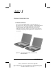
chapter 1 P RODUCT D ESCRIPTION 1.1 Models and Features The Compaq Armada E500, E500S, and Armada V300 Series of Personal Computers offer advanced modularity, Intel Pentium II, III, and Intel Celeron processors with 64-bit architecture, industry-leading Accelerated Graphics Port (AGP) implementation, and extensive multimedia support. The computers provide desktop functionality and connectivity through the optional expansion base, convenience base, or port replicator. Figure 1-1.
Models The Armada E500 and E500S model naming conventions are shown in Table 1-1. The computer model designation is composed of a group of characters that defines each model’s features.
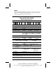
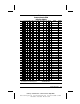
Table 1-2 Compaq Armada E500 Computer Models 1 2 3 4 5-6 7-9 10 11 12 13-14 15 16 17-19 20-21 22 23 24 A A A A A A A A A A A A A A A A A A A A A A A A A A A A A A A A A A 1 2 E E E E E E E E E E E E E E E E E E E E E E E E E E E E E E E E E E 5 5 5 5 5 5 5 5 5 5 5 5 5 5 5 5 5 5 5 5 5 5 5 5 5 5 5 5 5 5 5 5 5 5 P3 850 P3 850 P3 850 P3 850 P3 850 P3 850 P3 800 P3 800 P3 800 P3 800 P3 800 P3 800 P3 700 P3 700 P3 700 P3 700 P3 700 P3 700 P3 700 P3 700 P3 700 P3 700 P3 700 P3 700 P3 700 P3 700 P3 700 P3 700 P3
Table 1-2 continued 1 2 3 4 5-6 7-9 10 11 12 13-14 15 16 17-19 20-21 22 23 24 A A A A A A A A A A A A A A A A A A A A A A A A A A A A A A A A A A 1 2 E E E E E E E E E E E E E E E E E E E E E E E E E E E E E E E E E E 5 5 5 5 5 5 5 5 5 5 5 5 5 5 5 5 5 5 5 5 5 5 5 5 5 5 5 5 5 5 5 5 5 5 P3 700 P3 700 P3 700 P3 700 P3 700 P3 700 P3 700 P3 700 P3 700 P3 700 P3 650 P3 650 P3 650 P3 650 P3 650 P3 650 P3 650 P3 650 P3 650 P3 650 P3 650 P3 650 P3 600 P3 600 P3 600 P3 600 P3 600 P3 600 P3 600 P3 600 P3 600 P3 600
Table 1-2 continued 1 2 3 4 5-6 7-9 10 11 12 13-14 15 16 17-19 20-21 22 23 24 A A A A A A A A A A A A A A A A A A A A A A A A A A A A A A 1 E E E E E E E E E E E E E E E E E E E E E E E E E E E E E E 5 5 5 5 5 5 5 5 5 5 5 5 5 5 5 5 5 5 5 5 5 5 5 5 5 5 5 5 5 5 P3 600 P3 600 P3 600 P3 600 P3 600 P3 600 P3 600 P3 600 P3 600 P3 600 P3 600 P3 600 P3 500 P3 500 P3 500 P3 500 P3 500 P3 500 P3 500 P3 500 P3 500 P3 500 P3 500 P3 500 P3 500 P3 500 P3 500 P3 500 P3 500 P3 500 T T T T T T T T T T T T T T T T T T T
Table 1-2 continued 1 2 3 4 5-6 7-9 10 11 12 13-14 15 16 17-19 20-21 22 23 24 A A A A A A A A A A A A A A A A A A A A A A A A A A A 1 E E E E E E E E E E E E E E E E E E E E E E E E E E E 5 5 5 5 5 5 5 5 5 5 5 5 5 5 5 5 5 5 5 5 5 5 5 5 5 5 5 P3 500 P3 500 P3 500 P3 500 P3 500 P3 500 P3 500 P3 500 P3 500 P3 450 P3 450 P3 450 P3 450 P3 450 P3 450 P3 450 P3 450 P3 450 P2 400 P2 400 P2 400 P2 400 P2 400 P2 400 P2 400 P2 400 P2 400 T T T T T T T T T T T T T T T T T T T T T T T T T T T 2 2 2 2 2 2 2 2 2 4 4
Table 1-2 continued 1 2 3 4 5-6 7-9 10 11 12 13-14 15 16 17-19 20-21 22 23 24 A A A A A A A A A A A A A A A A A A A A A A A A A A A 1 E E E E E E E E E E E E E E E E E E E E E E E E E E E 5 5 5 5 5 5 5 5 5 5 5 5 5 5 5 5 5 5 5 5 5 5 5 5 5 5 5 P2 366 P2 366 P2 366 P2 366 P2 366 P2 366 P2 366 C1 600 C1 600 C1 600 C1 600 C1 600 C1 600 C1 600 C1 600 C1 600 C1 600 C1 600 C1 600 C1 600 C1 600 C1 600 C1 600 C1 600 C1 600 C1 600 C1 600 T T T T T T T T T T T T T T T T T T T T T T T T T T T 2 2 2 2 2 2 2 4 4 4 4
Table 1-2 continued 1 2 3 4 5-6 7-9 10 11 12 13-14 15 16 17-19 20-21 22 23 24 A A A A A A A A A A A A A A A A A A 1 E E E E E E E E E E E E E E E E E E 5 5 5 5 5 5 5 5 5 5 5 5 5 5 5 5 5 5 C1 550 C1 550 C1 550 C1 550 C1 550 C1 550 C1 550 C1 550 C1 550 C1 550 C1 550 C1 550 C1 550 C1 550 C1 550 C1 550 C1 550 C1 550 T T T T T T T T T T T T T T T T T T 4 4 3 3 3 3 3 3 3 3 2 2 2 2 2 2 2 2 X X X X X X X X X X S S S S S S S S 6 6 5 5 5 5 5 5 5 5 5 5 5 5 5 5 5 5 9-cell Lithium Ion main battery pack 1-8 D D
The Armada V300 model naming conventions are shown in Table 1-3. The computer model designation is composed of a group of characters that define each model’s features.
Table 1-4 Compaq Armada V300 Computer Models 1 2 3 4 5-6 7-9 10 11 12 13-14 15 16 17-19 20-21 22 23 24 SKU# Config.
Table 1-4 continued 1 2 3 4 5-6 7-9 10 11 12 13-14 15 16 17-19 20-21 22 23 24 SKU# Config.
Features The computer has the following features: ■ The Armada E500 and E500S feature the following processors, varying by computer model: ■ Intel Pentium III 850-, 800-, 700-, 650-, 600-, 500- or 450-MHz processor, with 256-KB integrated cache ■ Intel Pentium II 400- or 366-MHz, with 256-KB integrated cache ■ Intel Celeron 550-MHz, with 128-KB integrated cache ■ The Armada V300 features an Intel Celeron 500-, 466- or 400-MHz processor, with 128-KB integrated L2 cache, varying by computer model.
■ The following PC Card features are available, varying by computer model: ■ The Armada E500 and E500S feature two Type II PC Card slots with support for both 32-bit CardBus and 16-bit PC Cards; Zoomed video is supported in the bottom slot. ■ The Armada V300 features one Type II PC Card slot with support for both 32-bit CardBus and 16-bit PC Cards.
1.2 Intelligent Manageability Intelligent Manageability consists of preinstalled software tools for the computer and Compaq servers that assist in tracking, troubleshooting, protecting, and maintaining the computer. Intelligent Manageability provides the following functions: ■ Asset Management—provides detailed configuration and diagnostic information. ■ Fault Management—prevents, predicts, and alerts of impending hardware problems.
■ Inventory information—The network administrator can retrieve information about the computer over the network by using Compaq TM Insight Manager or any PC management tool provided by Compaq Solution Partners.
Fault Management Alerts Alerts can be enabled, disabled, and tested, and software can be set to back up information whenever a hard drive alert occurs. ■ While the computer is connected to a network, alerts pop up on the computer display and are simultaneously reported to the network console. ■ A system temperature alert reports overheating. As the system temperature rises, this feature first adjusts fan speed and other cooling components, then displays an alert, then shuts down the system.
Configuration Management Configuration Management optimizes software upgrade and customer. This support software is accessible through a monthly CD-ROM subscription. Support software can also be downloaded from the Compaq Web site at: www.compaq.com/support/portables Managing Power The computer comes with a collection of power management features that allow battery operating time to be extended and power to be conserved.
1.3 Computer External Components The external components on the display and left side of the computer are shown in Figure 1-2 and described in Table 1-5. Figure 1-2.
Table 1-5 Display and Left Side Components Item Component 1 2 Tilt feet (2) Battery bay Function Tilt the computer for ease of use. Accepts a 9- or 6-cell Lithium ion (Li ion) primary battery pack. 3 Armada E500 & E500S: Accepts a removable diskette drive or 9- or DualBay 6-cell Li ion primary battery pack. Armada V300: Accepts diskettes. Fixed diskette drive 4 Display release latch Opens the computer. 5 Audio bass port Enhances stereo sound.
The external components on the right side of the computer are shown in Figure 1-3 and are described in Table 1-6. Figure 1-3.
Table 1-6 Right Side Components Item Component Function 1 PC Card slots* 2 Stereo speaker/ headphone jack 3 Mono microphone jack 4 Security cable slot 5 RJ-11 jack (internal modem models only) 6 7 RJ-45 jack (internal network interface card models only) Infrared port Supports 32-bit (CardBus) and 16-bit PC Cards. Connects stereo speakers, headphones, or headset. This jack is driven by an amplifier and has volume control.
The external components on the rear of the computer are shown in Figure 1-4 and described in Table 1-7. Figure 1-4.
Table 1-7 Rear Components Item Component Function 1 2 AC Adapter connector Universal Serial Bus (USB) connector 3 4 External monitor connector Serial connector 5 Docking connector 6 Parallel connector 7 Keyboard/mouse connector Connects the AC power adapter. Connects USB devices, such as cameras for video conferencing, or hubs which connect multiple USB devices. The USB connector is a powered hub.
Computer keyboard components are shown in Figure 1-5 and described in Table 1-8. Figure 1-5.
Table 1-8 Keyboard Components Item Component 1 2 3 4 5 Power switch 6 Suspend button 7 8 9 10 11 12 12 Scroll lock key Num lock key Pointing stick Stereo speakers Left and right mouse buttons Fn key F1 through F12 function keys Function Information—links directly to Compaq Armada user information for quick answers to your computer questions. This key is present only on computer models with config. codes beginning with “FL5,” “FL6,” “FM,” “FV,” and “FW.
Additional computer keyboard components are shown in Figure 1-6 and described in Table 1-9. Figure 1-6.
Table 1-9 Keyboard Components (continued) Item Component Function 1 Hard drive light (green) 2 MultiBay light (green) 3 Num lock light 4 5 6 Caps lock light Scroll lock light Display switch 7 Page up and page down keys Embedded numeric keypad Cursor-control keys Windows application key TouchPad (TouchPad models only) Left and right TouchPad buttons (TouchPad models only) Microsoft logo key Caps lock key Turns on when the hard drive is being accessed.
The external components on the bottom of the computer are shown in Figure 1-7 and are described in Table 1-10. Figure 1-7. Bottom Components Table 1-10 Bottom Components Item Component Function 1 Mini PCI slot cover 2 3 Battery release latch Hard drive cover release latch Hard drive cover screw Hard drive cover Diskette drive release latch Contains the mini PCI modem or network interface card. Releases the battery from the battery bay. Releases the hard drive cover.
1.4 Design Overview This section presents a design overview of key parts and features of the computer. Refer to Chapter 3 for the illustrated parts catalog and Chapter 5 for removal and replacement procedures.
chapter 2 T ROUBLESHOOTING Follow these basic steps when beginning the troubleshooting process: 1. Complete the preliminary steps listed in Section 2.1. 2. Run the Power-On Self-Test (POST) as described in Section 2.3. 3. Run Computer Setup as described in Section 2.5. 4. If you are unable to run POST or if the problem persists after running POST, perform the recommended actions described in the diagnostic tables in Section 2.5.
The following table describes the troubleshooting actions: If You Want To: Then Run: Check for POST error messages POST Perform any of the following: Computer Setup ■ Check the system configuration ■ Set the system power management parameters ■ Return the system to its original configuration ■ Check system configuration of installed devices 2.1 Preliminary Steps IMPORTANT: Use AC power when running POST or Computer Setup. A low battery condition could initiate Hibernation and interrupt the test.
NOTE: If a problem only occurs when an external device is connected to the computer, the problem could be with the external device or its cable. Isolate the problem by running POST with and without the external device connected. 8. Use Compaq Utilities and loopback plugs in the serial and parallel connectors if you plan to test these ports. Follow these steps to run Compaq Utilities: a. If you are running Compaq Utilities from the hard drive, turn on or restart the computer.
2.3 Power-On Self-Test (POST) The Power-On Self-Test (POST) is a series of tests that run every time the computer is turned on. POST verifies that the system is configured and functioning properly. To run POST, complete the following steps: 1. Complete the preliminary steps (Section 2.1). 2. Turn on the computer. If POST does not detect any errors, the computer beeps once or twice to indicate that POST has run successfully.
If you receive one of the error messages listed below, follow the recommended action. Table 2-1 Warning Messages Message Description Recommended Action CMOS checksum invalid, run SCU CMOS RAM information has been corrupted. Run Computer Setup (Section 2.5) to reinitialize CMOS-RAM. CMOS failure, run SCU CMOS RAM has lost power. Run Computer Setup (Section 2.5) to reinitialize CMOS-RAM. Diskette controller error The diskette drive controller failed to respond to the recalibrate command.
Table 2-1 continued Message Description Recommended Action Keyboard failure The keyboard failed to respond to the RESET ID command. Replace the keyboard. If the problem persists, replace the system board. No interrupts from Timer 0 The periodic timer interrupt is not occurring. Replace the system board. ROM at xxxx (LENGTH yyyy) with nonzero checksum (zz) An illegal adapter ROM was located at the specified address.
Fatal errors emit a beep and may display a FATAL message. Fatal errors indicate severe problems, such as a hardware failure. Fatal errors do not allow the system to resume. Some of the Fatal error beep codes are listed at the end of this section. Table 2-2 Fatal Error Messages Message Description Beep code CMOS RAM test failed A walking bit test of CMOS RAM location 0E (Hex) - 3F (Hex) failed.
Table 2-3 Fatal Error Beep Codes Beep Code Beep Sequence Description Recommended Action 0 S-S-S-P-S-S-L-P The DMA page registers are faulty. Replace system board. 1 S-S-S-P-S-L-S-P The refresh circuitry is faulty. 2 S-S-S-P-S-L-L-P The ROM checksum is incorrect. 3 S-S-S-P-L-S-S-P The CMOS RAM test failed. 4 S-S-S-P-L-S-L-P The DMA controller is faulty. 5 S-S-S-P-L-L-S-P The interrupt controller failed. 6 S-S-S-P-L-L-L-P The keyboard controller failed.
2.5 Compaq Utilities Compaq Utilities contain several functions that: ■ Determine if various computer devices are recognized by the system and are operating properly ■ Provide information about the system once it is configured. Compaq Utilities include the following programs: ■ Computer Setup ■ Compaq Diagnostics To access Compaq Utilities: 1. Turn on or restart the computer by clicking Start!Shut Down!Restart the computer. 2.
Using Computer Setup All information and settings in Computer Setup are accessed from the File, Security, or Advanced menus. NOTE: Your settings in Computer Setup are not affected by updating the system ROM. To view information or change a setting in Computer Setup: 1. Turn on or restart the computer. When the blinking cursor appears in the upper-right corner of the screen, press F10. ■ To change the language, press F2. ■ To view navigation information, press F1.
The following sections provide detailed instructions on using the File, Security, and Advanced menus. File Menu Begin here System information To do this ■ View identification information about the computer, docking base, and battery packs ■ View specification information about the processor, memory and cache size, and ROM date and family Save to floppy Save system configuration to a diskette Restore from floppy Restore system configuration from a diskette.
Security Menu Begin here To do this Setup password Enter, change, or delete a setup password Power-on password Enter, change, or delete a power-on password Password options Enable/disable: ■ QuickLock/QuickBlank ■ Lock keyboard and pointing stick or touchpad at startup (These features can be enabled only when a power-on password is set.
Advanced Menu Begin here To do this Language (or press F2) Change the Computer Setup language Boot Options Enable/disable: ■ QuickBoot, which starts the computer more quickly by eliminating some startup tests (If you suspect a memory failure and want to test memory automatically during startup, you may want to disable QuickBoot.
Using Compaq Diagnostics for Windows 1. Access Compaq Diagnostics for Windows by selecting Start!Settings!Control Panel!Compaq Diagnostics. 2. To select a category, choose one of two methods: ■ Select the Categories menu, then select a category from the drop-down list. ■ Select a category icon on the toolbar. 3. To run diagnostic tests: a) Select the Test tab. b) In the scroll box, select the category or device you want to test. c) Select the Quick, Complete, or Custom test type.
Factory Default Settings Table 2-4 Initialization Enable POST Memory Test Checked (enabled) Keyboard Num Lock Unchecked (off) Hard drive boot sequence 1 Hard drive in the computer MultiBay 2 Hard drive in the computer hard drive bay Boot display Auto Language Language of country Table 2-5 Ports Serial port 3F8, IRQ4 Infrared port 2F8, IRQ9 Parallel port 378, IRQ7 Ethernet port 300, IRQ11 Troubleshooting COMPAQ CONFIDENTIAL - NEED TO KNOW REQUIRED Writer: David Calvert Saved by: The Inte
Table 2-6 Power Low Battery Warning Beep Checked (enabled) External Energy Saving Monitor Connected Unchecked (not connected) Power Management Enabled While operating on battery power Conservation Level High Level Definition High Suspend Time: 3 minutes Hibernation Timeout: Immediate Drive Timeout: 1 minute Screen Timeout: 1 minute Medium Suspend Time: 5 minutes Hibernation Timeout: 1 hour Drive Timeout: 2 minutes Screen Timeout: 3 minutes Custom Allows the desired times to be customized.
2.6 Troubleshooting Without Diagnostics This section provides information about how to identify and correct some common hardware, memory, and software problems. It also explains several types of messages that are displayed on the screen. Since symptoms can appear to be similar, carefully match the symptoms of the computer malfunction against the problem description in the Troubleshooting tables to avoid a misdiagnosis.
Table 2-8 Solving Audio Problems Problem Possible Cause Computer does not System beeps have beep after the Power- been turned down. On Self-Test (POST). Internal speaker does Volume may be not produce sound turned off or set too when an external low. audio source is connected to the stereo line-in jack. External microphone does not work. Solution Use the Fn+F5 hotkeys to turn up the system volume. ■ Adjust the overall volume by pressing the Fn+F5 hotkeys.
Table 2-8 continued Problem Possible Cause Solution External microphone does not work (continued). Sound source is not selected. Ensure that microphone is selected as the recording source in Control Panel ! Multimedia and that the recording level is adjusted. Audio settings are not set correctly. Check the game program's audio settings. Volume control on the computer is turned down. Adjust the computer volume with the Fn+F5 hotkeys. Volume or mixing controls are set incorrectly.
Table 2-9 Solving Battery/Battery Gauge Problems Problem Possible Cause Computer is beeping and battery power light is blinking. Battery pack charge is low. Solution ■ Charge the battery pack by connecting it to an external power source. ■ Replace the battery pack with another fully charged battery. ■ Initiate Hibernation or turn the computer off until AC power or a fully charged battery is available. Computer battery charge light blinks to indicate low battery condition, but computer does not beep.
Table 2-9 continued Problem Possible Cause Solution Battery charge does not last very long (continued). Battery was exposed Move the computer to a to extremely cold warmer place and temperatures. recharge the battery pack. NOTE: The recommended operating temperature range for the battery is from 10°C to 40°C (50°F to 104°F). The recommended storage temperature range for the battery is from 0°C to 30°C (32°F to 86°F). Battery conservation Reset the battery is disabled or set to conservation level. drain.
Table 2-10 Solving Compact Disc and DVD-ROM Problems Problem Possible Cause Solution Drive cannot read a disc Disc is not properly seated in the drive. Open the loading tray, insert the disc, then close the tray. Disc is loaded in the loading tray upside down. Open the loading tray, turn over the disc (label facing up), then close the tray. Disc has a scratch on its surface. Insert a different disc. Drive is not connected properly.
Table 2-11 Solving Diskette Drive/SuperDisk LS-120 Drive Problems Problem Possible Cause Solution Drive cannot write to a diskette. Diskette is not formatted. Format the diskette. Diskette is write-protected. Use another diskette that is not write-protected or disable the write-protect feature. Writing to the wrong drive Check the drive letter in your path statement. Not enough space is Save the information to left on the diskette. another diskette.
Table 2-12 Solving Hard Drive Problems Problem Possible Cause Solution Accessing information on the hard drive is much slower than usual. Hard drive entered low power state due to timeout and is now exiting from it. Wait for the system to restore the previously saved data prior to initiating a low power state. Hard drive is fragmented/not optimized or has errors. Run ScanDisk and Disk Defragmenter. Hard drive does not work. Hard drive is not seated properly.
Table 2-13 Solving Infrared Problems Problem Possible Cause Solution Cannot communicate The appropriate with another software is not computer running on both computers. Install the appropriate software on the second device, start the second device, and start the program on both computers. The other computer Communication between does not have an infrared devices must use IrDA-compliant the same communications infrared port. Your protocol.
Table 2-13 continued Problem Possible Cause Solution Cannot transmit data Direct sunlight, fluorescent light, or flashing incandescent light is close to the infrared connections. Remove any interfering light sources. There is interference Keep remote control units from other wireless such as wireless devices. headphones and other audio devices away from the infrared connections. There is a physical obstruction in the way.
Table 2-14 Solving Keyboard Problems Problem Possible Cause Solution Screen is blank and keyboard is working. A screen timeout has been initiated. Press any key to refresh the screen. QuickLock/QuickBlank has been initiated. To enable the keyboard and return your information to the screen, enter your power-on password. LCD has been disabled. Press Fn+F4 to cycle from external monitor to internal LCD. Embedded Num Lock function is numeric keypad on not turned on. computer keyboard is disabled.
Table 2-15 Solving Modem Problems Problem Possible Cause Solution Modem loses connection. The cable connection from the phone line to the modem is loose. Ensure that the telephone cable is properly connected. Call Waiting has not been disabled. Disable Call Waiting: Select Start ! Setting ! Control Panel ! Modems. From the General tab of the Modems Properties page, select Dialing Properties.
Table 2-15 continued Problem Possible Cause Solution Modem does not dial correctly. Telephone number is ■ Make sure the not entered correctly telephone number you in the modem’s dialed is correct if you dialing software. are using the dialing directory or the terminal mode. ■ Dial 1 if using dialing long distance. ■ The other line could be busy or not answering. Try again later. ■ Make sure call waiting is disabled. ■ The modem may not recognize an international dial tone.
Table 2-15 continued Problem Possible Cause Solution Phone line noise is causing a disconnection. Hang-up Delay S Register (S10) is set too low. No dial tone Phone service is not connected to the telephone wall jack. Change S10 default to 150. To set S10=150: 1. Select Start ! Programs ! Accessories ! HyperTerminal, then go to Command Mode. 2. Type ATS10=150 and press Enter. This command causes the modem to take longer to disconnect even if there is noise on the line.
Table 2-15 continued Problem Possible Cause Solution No dial tone (continued) The modem is not responding to commands from the computer keyboard. Verify the modem and computer are connected: 1. Select Start ! Programs ! Accessories ! HyperTerminal, then go to Terminal Mode. 2. Type AT and press the Enter key. If the modem displays OK, the modem and computer are working together. If the modem displays ERROR, or does not respond, restart the computer and repeat step 1. 3.
Table 2-15 continued Problem Possible Cause Solution Modem does not connect at highest speed (continued). The service or site called does not support 56K or supports an incompatible 56K implementation. An internal modem supports K56flex. To find an Internet service provider (ISP) that supports K56flex, go to the Compaq Web site at: www.compaq.com There is noise on the The 56K protocol of an telephone line.
Table 2-16 Solving PC Card Problems Problem Possible Cause Solution Computer does not beep when a PC Card is inserted. PC Card is not inserted properly. Try reinserting the card. Ensure that the PC Card is inserted in the correct orientation. Insert the card gently to prevent damage to the pins. Speakers are turned off or volume is turned down. Adjust the volume control on the computer. PC Card or card Check the list of PC driver is not PCMCIA Cards tested successfully compliant.
Table 2-16 continued Problem Possible Cause Solution Network PC Card does not work (continued). Network PC Card or Check the list of PC driver is not PCMCIA Cards tested successfully compliant. in Compaq PC Card platforms. Storage PC Card does not work. SRAM and flash memory PC Cards require the memory card driver to be loaded. Memory cards can only be accessed using DOS real mode drivers. Ensure that the correct drivers are loaded.
Table 2-17 Solving Power Problems Problem Possible Cause Computer will not turn on. Battery is discharged and computer is not connected to a power source. ■ Charge the battery pack. Battery is discharged and cables to the external power source are unplugged. Ensure that cables connecting the computer and the external power source are plugged in properly. Computer turned off Computer initiated while it was left power-down unattended. because of a critical low battery condition.
Table 2-18 Solving Display Problems Problem Possible Cause Solution Characters on computer display are dim. Computer is in directMove the computer or adjust the screen. light. The brightness control is not set properly. Adjust the brightness control by pressing the Fn+F10 hotkeys. You may have a screen saver or screen blanking utility installed. Press any key to refresh the screen. Screen timeout was initiated. Press any key to light the screen.
Table 2-18 continued Problem Possible Cause Characters on computer display are dim (continued). Power Management, which controls Suspend and Hibernation, is disabled and the battery pack has discharged. Computer screen is blank and external monitor displays information. Solution ■ Replace the battery pack and turn on the computer. ■ Connect the computer to an external power source and turn on the computer. Display was switched to the external monitor.
Table 2-19 Solving USB Problems 2-38 Problem Possible Cause Solution External device connected to a USB connector does not work. The operating system limits external devices connected by USB to two tiers that can include no more than two hubs on the first tier and no more than one keyboard and one pointing device on the first or second tier.
chapter 3 I LLUSTRATED P ARTS C ATALOG This chapter provides an illustrated parts breakdown and a reference for spare part numbers and option part numbers for the Compaq Armada E500, E500S, and Armada V300 Series of Personal Computers. 3.1 Serial Number Location When ordering parts or requesting information, provide the computer serial number and model number located on the bottom of the computer (Figure 3-1). Figure 3-1.
3.2 Computer System Major Components Figure 3-2.
Table 3-1 Spare Parts: Computer System Major Components Item 1 2a 2b 2c 2d 2e 2f 2g 2h Description Spare Part Number Display assembly 15.0-inch, TFT, SXGA (Armada E500 and 201059-001 E500S only); used only with config. codes beginning with JFC. 15.0-inch, TFT, XGA (Armada E500 and 190806-001 E500S only); used only with config. codes beginning with DX and FFH. 14.1-inch, TFT, XGA; used only with config.
Computer System Major Components (continued) 3-4 Illustrated Parts Catalog COMPAQ CONFIDENTIAL - NEED TO KNOW REQUIRED Writer: The Integrity Group Saved by: The Integrity Group Saved date: 10/26/00 12:34 PM Part Number: 128679-006 File name: Ch03
Table 3-1 continued Item 3 4 5a 5b 6 Description Spare Part Number LED board used with all config. codes except those beginning with FL5, FL6, FM, FV, FW, and JF. used with all config. codes beginning with FL5, FL6, FM, FV, FW, and JF. Keyboard with pointing stick (Armada E500 and E500S only) Latin American -181 Belgian Spanish -201 Brazilian Norwegian -081 Danish Portuguese -051 French Spanish French Canadian -121 Swedish -041 German Swiss -002 International Taiwanese -061 Italian U.K.
Computer System Major Components (continued) 3-6 Illustrated Parts Catalog COMPAQ CONFIDENTIAL - NEED TO KNOW REQUIRED Writer: The Integrity Group Saved by: The Integrity Group Saved date: 10/26/00 12:34 PM Part Number: 128679-006 File name: Ch03
Table 3-1 continued Item 7 Description Spare Part Number System board Armada E500 and E500S only (all with 64 MB SDRAM) Intel Pentium III 850-MHz processor; used only with config. codes beginning with JFC. Intel Pentium III 800-MHz processor; used only with config. codes beginning with JFB. Intel Pentium III 700-MHz processor; used only with config. codes beginning with: DX FMX FMZ FWZ JFF FFH Intel Pentium III 650-MHz processor; used only with config.
Computer System Major Components (continued) 3-8 Illustrated Parts Catalog COMPAQ CONFIDENTIAL - NEED TO KNOW REQUIRED Writer: The Integrity Group Saved by: The Integrity Group Saved date: 10/26/00 12:34 PM Part Number: 128679-006 File name: Ch03
Table 3-1 continued Item 7 8 Description Spare Part Number System board (continued) Armada V300 only Intel Celeron 500-MHz processor with 64 MB SDRAM; used only with config. codes beginning with DVR. Intel Celeron 466-MHz processor with 64 MB SDRAM; used only with config. codes beginning with DVP. Intel Celeron 466-MHz processor with 64 MB SDRAM; used only with config.
Computer System Major Components (continued) 3-10 Illustrated Parts Catalog COMPAQ CONFIDENTIAL - NEED TO KNOW REQUIRED Writer: The Integrity Group Saved by: The Integrity Group Saved date: 10/26/00 12:34 PM Part Number: 128679-006 File name: Ch03
Table 3-1 continued Item 9 10 11a 11b 12 13 14 Description Spare Part Number Li ion battery pack, 9 cell (also available as an option) Li ion battery pack, 6 cell (also available as an option) CPU base enclosure Removable diskette drive (Armada E500 and E500S only) Fixed diskette drive (Armada V300 only) Removable hard drive 20.0 GB (Armada E500 and E500S only) 18.0 GB (Armada E500 and E500S only; available only as an option) 12.0 GB (Armada E500 and E500S only) 10.0 GB (Armada E500 and E500S only) 6.
3.3 Miscellaneous Plastics Kit Components Figure 3-3. Miscellaneous Plastics Kit Components Table 3-2 Miscellaneous Plastics Kit Components Spare Part Number 159536-001 Item 1a 1b 2 3 4 5 6 7 8 9 10 11 12 13 14 15 16 3-12 Description Switch cover does not include Easy Access buttons; used with config. codes not beginning with FL5, FL6, FM, FV, and FW. includes Easy Access buttons; used with config. codes beginning with FL5, FL6, FM, FV, FW, and JF.
3.4 Mass Storage Devices Figure 3-4. Mass Storage Devices Table 3-3 Spare Parts: Mass Storage Devices Item 1 2 3 4 5 6 Description Hard drive 20.0 GB (Armada E500 and E500S only) 18.0 GB (Armada E500 and E500S only; available only as an option) 12.0 GB (Armada E500 and E500S only) 10.0 GB (Armada E500 and E500S only) 6.0 GB (Armada E500 and E500S only) 5.0 GB 4.3 GB 10.0 GB (available only as an option) 24X CD-ROM drive 4X CD-RW drive 8X DVD-ROM drive 4X DVD-ROM drive Removable diskette drive, 1.
3.5 Miscellaneous Table 3-4 Spare Parts: Miscellaneous (not illustrated) Description Spare Part Number AC Adapter, 50 W 163444-001 or 101898-001* * When ordering an AC Adapter, use the spare part number on the part number label of the adapter being replaced.
chapter 4 R EMOVAL AND R EPLACEMENT P RELIMINARIES This chapter provides essential information for proper and safe removal and replacement service. 4.
Plastic Parts Using excessive force during disassembly and reassembly can damage plastic parts. Use care when handling the plastic parts. Apply pressure only at the points designated in the maintenance instructions. Cables and Connectors Cables must be handled with extreme care to avoid damage. Apply only the tension required to unseat or seat the cables during removal and insertion. Handle cables by the connector whenever possible. In all cases, avoid bending, twisting, or tearing cables.
■ After removing a hard drive, CD-ROM drive, or a diskette drive, place it into a static-proof bag. ■ Do not use excessive force when inserting a drive into a drive bay. ■ After inserting a hard drive into the hard drive bay, always reinsert either the original hard drive security plate or the tamper-resistant security plate to prevent the hard drive from accidentally disconnecting. ■ Avoid exposing a hard drive to products that have magnetic fields such as monitors or speakers.
4.5 Packaging and Transporting Precautions Use the following grounding precautions when packaging and transporting equipment: ■ To avoid hand contact, transport products in static-safe containers such as tubes, bags, or boxes. ■ Protect all electrostatic-sensitive parts and assemblies with conductive or approved containers or packaging. ■ Keep electrostatic-sensitive parts in their containers until they arrive at static-free workstations.
■ Avoid contact with pins, leads, or circuitry. ■ Turn off power and input signals before inserting or removing connectors or test equipment. 4.7 Grounding Equipment and Methods Grounding equipment must include either a wrist strap or a foot strap at a grounded workstation. ■ When seated, wear a wrist strap connected to a grounded system. Wrist straps are flexible straps with a minimum of one megaohm ±10% resistance in the ground cords.
Table 4-1 shows how humidity affects the electrostatic voltage levels generated by different activities.
chapter 5 R EMOVAL AND R EPLACEMENT P ROCEDURES This chapter provides removal and replacement procedures for the Compaq Armada E500, E500S, and Armada V300 Series of Personal Computers. 5.1 Serial Number Report the computer serial number to Compaq when requesting information or ordering spare parts. The serial number is located on the bottom of the computer (Figure 5-1). Figure 5-1.
5.2 Disassembly Reference Chart Use the chart below to determine the section number to be referenced when removing components from the computer. Disassembly Sequence Chart 5.3 Preparing the Computer for Disassembly 5.4 Computer Feet 5.5 Mini PCI Slot Removing the Mini PCI Slot Cover Installing a Modem or Modem/Network Interface Card 5.6 Touch Button 5.7 Keyboard 5.8 Memory Removing a Memory Expansion Board Installing a Memory Expansion Board 5.9 Display Assembly 5.10 Real Time Clock (RTC) Battery 5.
4. If installed, remove the diskette drive from the DualBay (Armada E500 only). 5. Remove the hard drive from the hard drive bay. 6. Remove any devices installed in the MultiBay. 5.4 Computer Feet The base feet are oblong, adhesive-backed rubber pads. The base feet are included in the Miscellaneous Plastics Kit.
5.5 Mini PCI Slot Modem and Modem/Network Interface Card Spare Part Number Information Mini PCI V. 90 modem card 121895-001 Mini PCI V. 90 modem/Network Interface Card 153207-001 Removing the Mini PCI Slot Cover 1. Prepare the computer for disassembly (Section 5.3). 2. Turn the computer bottom side up with the front facing forward. 3. Remove the two screws 1 that secure the mini PCI slot cover to the base enclosure (Figure 5-3). 4.
Installing a Modem or Modem/Network Interface Card 1. Remove the mini PCI slot cover. 2. Remove the two screws 1 that secure the modem or modem/NIC to the system board (Figure 5-4). 3. Make sure the appropriate RJ11/RJ45 covers are removed from the base enclosure. 4. Install the card into the mini PCI slot, making sure to seat the card connector on the system board 2. Figure 5-4.
5.6 Touch Button Touch Button Spare Part Number Information Touch Button without TouchPad (Armada E500 only) Touch Button 3 with TouchPad Touch Button with TouchPad 159530-001 188645-001 135227-001 Removing the Touch Button 1. Prepare the computer for disassembly (Section 5.3). 2. Position the computer with the front facing forward. 3. Open the computer. 4. Use a flat blade screwdriver to pry the upper right corner of the touch button away from the top cover 1 (Figure 5-5). 5.
8. Disconnect the touch button cable from the touch button (Figure 5-6). NOTE: The touch button cable is included in the Miscellaneous Plastics Kit.
5.7 Keyboard Keyboard with Pointing Stick Spare Part Number Information (Armada E500 only) Keyboard with Pointing Stick Brazilian -201 Italian Belgian -181 International Danish -081 Japanese French -051 Korean French Latin American Spanish Canadian -121 -041 Norwegian German Portuguese -061 -002 -291 -AD1 -161 -091 -131 154876-XXX Spanish Swedish Swiss Taiwanese U.K. English U.S.
Removing the Keyboard 1. Prepare the computer for disassembly (Section 5.3). 2. Turn the computer bottom side up with the front facing forward. 3. Remove the screw that secures the keyboard (Figure 5-7). Figure 5-7.
4. Turn the computer right side up with the front facing forward. 5. Open the computer. 6. Slide the four latches 1 located along the top of the keyboard forward. 7. Swing the back edge of the keyboard 2 up and forward (Figure 5-8). Figure 5-8.
8. Release the ZIF (Zero Insertion Force) connector that connects the keyboard cable 1 (Figure 5-9). 9. Disconnect the keyboard cable from the system board 2. 10. (Armada E500 only) Release the ZIF connector that connects the pointing stick cable 3. 11. (Armada E500 only) Disconnect the pointing device cable from the system board 4. Figure 5-9. Releasing and Disconnecting the Keyboard Cables 12. Remove the keyboard. Reverse the removal procedure described above to replace the keyboard.
5.8 Memory The Compaq Armada E500 and Armada V300 Series feature two memory expansion slots, located under the keyboard. Depending on the computer model, one slot will contain a 64- or 32-MB memory expansion board. ! WARNING: Failure to unplug the power cord and remove the battery pack before installing a memory expansion board can damage the equipment and expose you to the risk of electrical shock. CAUTION: Electrostatic discharge (ESD) can damage electronic components.
Removing a Memory Expansion Board 1. Prepare the computer for disassembly (Section 5.3). 2. Remove the keyboard (Section 5.7). 3. Spread the retaining tabs apart 1. The memory expansion board tilts upward (Figure 5-10). 4. Lift the edge of the memory expansion board and slide it gently out of the memory expansion slot at a 45-degree angle 2. 5. Place the memory expansion board in an electrostatic-safe container. Figure 5-10.
Installing a Memory Expansion Board All memory expansion boards are asymmetrically keyed (notched) to ensure correct positioning. Memory expansion boards can be used in either memory expansion slot. 1. Insert the memory expansion board into an empty memory expansion slot at a 45-degree angle 1 (Figure 5-11). 2. Push the memory expansion board down 2 until the board is seated in the plastic retention clips. Figure 5-11. Installing a Memory Expansion Board 3. Run Computer Setup (refer to Section 2.5).
5.9 Display Assembly Display Assembly Spare Part Number Information 15.0-inch, TFT, SXGA (Armada E500 only); used only with config. codes beginning with JFC. 15.0-inch, TFT, XGA (Armada E500 only); used only with config. codes beginning with DX and FFH. 14.1-inch, TFT, XGA; used only with config. codes beginning with: CXX DJD4 DN85 FFD FWX CZQ DN81 DN9 FLC FVX DC DN82 DPB FMX JFB DJD3 DN84 DVR FMZ JFD 13.3-inch, TFT, XGA (Armada E500 only) DN83 FL5 FWB JFF JFH DNN FL6 13.
Removing the Display 1. Prepare the computer for disassembly (Section 5.3). 2. Position the computer so the rear panel faces forward (Figure 5-12). 3. Remove the screws that secure the hinge cover 1 and switch cover 2. 4. Lift the hinge cover up 3 and remove it. Figure 5-12. Removing the Switch and Hinge Cover Screws 5. Open the computer as far as it will open.
6. Push the back of the switch cover up 1 (Figure 5-13). 7. Position the computer so the front faces forward. 8. Swing the switch cover up and forward 2. 9. Remove the switch cover. Figure 5-13.
NOTE: The hinge and switch covers are spared in the Miscellaneous Plastics Kit. There are two switch covers in the Miscellaneous Plastics Kit: the switch cover containing the Easy Access buttons is used only on computer models with config. codes beginning with FL5, FL6, FM, FV, FW, and JF. The switch cover that does not contain the Easy Access buttons is used on all other computer models.
10. Remove the screws 1 that secure the display ground cables (Figure 5-14). 11. Disconnect the display panel 2, microphone 3 and display inverter cables 4 from the system board. Figure 5-14.
12. Position the computer so the rear panel faces forward. 13. Remove the two screws that secure the display assembly to the base enclosure 1 (Figure 5-15). NOTE: When these screws are removed, the display assembly is unsupported. Make sure to provide support for the display assembly when removing these screws. 14. Remove the display assembly 2. Figure 5-15. Removing the Display Assembly Reverse the removal procedure described above to replace the display assembly.
5.10 Real Time Clock (RTC) Battery The RTC battery is spared in the Miscellaneous Plastics Kit.
5.11 LED Board LED Board Spare Part Number Information LED board used with all config. codes except those beginning with FL5, FL6, FM, FV, FW, and JF. used with all config. codes beginning with FL5, FL6, FM, FV, FW, and JF. 159539-001 201058-001 Removing the LED Board 1. Prepare the computer for disassembly (Section 5.3) 2. Remove the switch cover (Section 5.9). 3. Disconnect the display ground cables (Section 5.9) and RTC battery cable (Section 5.10) from the LED board. 4.
5.12 Top Cover Top Cover Spare Part Number Information Top cover without TouchPad 159533-001 Removing the Top Cover 1. Prepare the computer for disassembly (Section 5.3) and, in the order below, remove the following components: ■ Touch button (Section 5.6) ■ Keyboard (Section 5.7) ■ Display assembly (Section 5.9) ■ LED board (Section 5.11) 2. Turn the computer bottom side up with the front facing forward. 3.
NOTE: The diskette drive bezel is spared in the Miscellaneous Plastics Kit. Diskette Drive Bezel Spare Part Number Information Miscellaneous Plastics Kit, includes: Switch cover (2) Hinge cover Real time clock (RTC) battery Touch button cable Front shield Diskette drive bezel Hard drive cover Mini PCI slot cover 159536-001 RJ-11 modem cover RJ-45 LAN cover Computer feet Display screw covers TV out connector cover PC Card space saver Diskette drive space saver CD-ROM drive space saver Infrared lens 6.
7. Turn the computer top side up with the rear panel facing forward. 8. Remove the screw 1 that secures the top cover to the base enclosure (Figure 5-20). 9. Disconnect the left 2 and right 3 speaker cables from the system board. Figure 5-20.
10. Lift the back edge of the top cover 1 and swing it forward 2 (Figure 5-21). Figure 5-21. Removing the Top Cover 11. Remove the top cover. Reverse the removal procedure described above to replace the top cover.
5.13 Front Shield The front shield is spared in the Miscellaneous Plastics Kit.
3. Remove the screw 1 that secures the front shield to the base enclosure (Figure 5-22). 4. Lift the front edge of the front shield up and swing it toward the back of the computer 2. Figure 5-22. Removing the Front Shield 5. Remove the front shield. Reverse the removal procedure described above to replace the front shield.
5.14 Diskette Drive (Armada V300 only) Diskette Drive Spare Part Number Information Diskette drive 160537-001 Removing the Diskette Drive 1. Prepare the computer for disassembly (Section 5.3) and, in the order below, remove the following components: ■ Touch button (Section 5.6) ■ Keyboard (Section 5.7) ■ Display assembly (Section 5.9) ■ LED board (Section 5.11) ■ Top cover (Section 5.12) 2. Release the ZIF connector that connects the diskette drive 1 (Figure 5-23). 3.
5.15 System Board IMPORTANT: When replacing the system board, remove the voltage converter board and retain it for use on the new system board. A new voltage converter board is not shipped with the new system board. Refer to Section 5.16 for voltage converter board removal procedures. System Board Spare Part Number Information Armada E500 only (all with 64 MB SDRAM) Intel Pentium III 850-MHz processor; used only with config. codes beginning with JFC.
System Board continued Armada V300 only Intel Celeron 500-MHz processor with 64 MB SDRAM; used only with config. codes beginning with DVR. Intel Celeron 466-MHz processor with 64 MB SDRAM; used only with config. codes beginning with DVP. Intel Celeron 466-MHz processor with 64 MB SDRAM; used only with config. codes beginning with: CXX DJD3 DJD4 DVQ Intel Celeron 400-MHz processor with 64 MB SDRAM; used only with config.
2. Turn the computer bottom side up with the front facing forward. 3. Disconnect the battery terminal cable from the system board (Figure 5-24). Figure 5-24.
4. Turn the computer top side up with the rear panel facing forward. 5. Remove the two bushing guides 1 that secure the system board to the I/O bracket (Figure 5-25). 6. Remove the three screws 2 that secure the system board to the base enclosure. 7. Lift the system board straight out of the base enclosure 3. Figure 5-25. Removing the System Board Reverse the removal procedure described above to replace the system board.
5.16 Voltage Converter Board IMPORTANT: When replacing the system board, remove the voltage converter board and retain it for use on the new system board. A new voltage converter board is not shipped with the new system board. Voltage Converter Board Spare Part Number Information Voltage converter board 152928-001 Removing the Voltage Converter Board 1. Prepare the computer for disassembly (Section 5.
3. Lift the left and right edges of the voltage converter board to disconnect it from the system board (Figure 5-26). Figure 5-26. Removing the Voltage Converter Board 4. Remove the voltage converter board. Reverse the removal procedure described above to replace the voltage converter board.
5.17 Fan IMPORTANT: The fan must be replaced only by central repair depot personnel. Fan Spare Part Number Information Fan 159535-001 Removing the Fan 1. Prepare the computer for disassembly (Section 5.3) and, in the order below, remove the following components: ■ Modem or modem/Network Interface Card (Section 5.5) ■ Touch button (Section 5.6) ■ Keyboard (Section 5.7) ■ Display assembly (Section 5.9) ■ LED board (Section 5.11) ■ Top cover (Section 5.12) ■ Front shield (Section 5.
3. Remove the six screws that secure the fan and heat sink to the system board 1 (Figure 5-27). 4. Disconnect the fan cable from the system board 2. 5. Remove the fan and heat sink from the system board 3. Figure 5-27.
6. Remove the two screws that secure the fan to the heat sink 1 (Figure 5-28). 7. Remove the fan from the heat sink 2. Figure 5-28. Removing the Fan Reverse the removal procedure described above to replace the fan and heat sink.
chapter 6 P RODUCT D ESCRIPTION This chapter provides physical and performance specifications for the Armada E500, E500S, and Armada V300 Personal Computers. Table 6-1 Computer Dimensions Height Depth Width U.S. Metric 1.65 inch 9.99 inch 12.40 inch 41.8 cm 316.0 cm 254.0 cm Weight 5.7 to 7.0 pounds, 2.60 to 3.20 kilograms, depending on depending on configuration configuration Standalone (Battery) Power Requirements Nominal operating voltage (Li ion) 10.
Table 6-1 continued U.S. Metric Altitude (unpressurized) Operating 0 to 10,000 ft 0 to 3048 m Nonoperating 0 to 30,000 ft 0 to 9144 m Shock 10 G, 11 ms, half sine Operating Nonoperating 240 G, 2 ms, half sine Vibration 0.5 G zero to peak, 10 to 500 Hz, 0.25 oct/min Operating Nonoperating 1.5 G zero to peak, 10 to 500 Hz, 0.50 oct/min NOTE: Applicable product safety standards specify thermal limits for plastic surfaces. The computer operates well within this range of temperatures. Table 6-2 15.
Table 6-3 15.0-inch XGA, TFT Display U.S. Metric Dimensions Height Width Diagonal 8.98 inch 11.97 inch 15.00 inch 22.81 cm 30.41 cm 38.01 cm Number of Colors Up to 16.8 million Contrast Ratio 150:1 Brightness 130 nits minimum, 150 nits typical Pixel Resolution Pitch Format Configuration 1024 × 768 RGB Stripe Backlight Edge Lit Total Power Consumption 4.50 W 0.297 × 0.297 mm Table 6-4 14.1-inch XGA, TFT Display U.S. Metric Dimensions Height Width Diagonal 8.46 inch 11.22 inch 14.
Table 6-5 13.3-inch XGA, TFT Display U.S. Metric Dimensions Height Width Diagonal 7.98 inch 10.64 inch 13.30 inch 20.28 mm 27.03 mm 33.79 mm Number of Colors Up to 16.8 million Contrast Ratio 100:1 Brightness 120 nits minimum, 150 nits typical Pixel Resolution Pitch Format Configuration 1024 × 768 RGB stripe Backlight Edge lit Total Power Consumption 4.10 W 6-4 0.264 × 0.
Table 6-6 12.1-inch SVGA, TFT Display U.S. Metric Dimensions Height Width Diagonal 7.24 inch 9.70 inch 12.10 inch 18.40 cm 24.60 cm 30.70 cm Number of Colors Up to 16.8 million Contrast Ratio 150:1 Brightness 120 nits minimum, 150 nits typical Pixel Resolution Pitch Format Configuration 800 × 600 RGB Stripe Backlight Edge Lit Total Power Consumption 3.50 W 0.300 × 0.300 mm Table 6-7 12.1-inch SVGA, STN Display U.S. Metric Dimensions Height Width Diagonal 7.24 inch 9.70 inch 12.
Table 6-8 Hard Drives 20.0 GB 18.0 GB 12.0 GB 10.0 GB 6.0 GB 20.0 GB 18.0 GB 12.0 GB 10.0 GB 6.0 GB User capacity 1 per drive Drive height (with 9.5 9.5 9.5 9.5 9.5 drive frame, in mm) Drive width (with 70.0 70.0 70.0 70.0 70.0 drive frame, in mm) 2.5-inch form Yes Yes Yes Yes Yes factor Interface type ATA-5 ATA-4 ATA-4 ATA-5 ATA-4 3 Seek times (typical, including setting) Single track 2.5 ms 2.5 ms 2.5 ms 2.5 ms 2.5 ms Average 12.0 ms 12.0 ms 12.0 ms 12.0 ms 12.0 ms Full stroke 23.0 ms 23.0 ms 23.
Table 6-9 Diskette Drive Diskette Size Light Height Bytes per sector Sectors per track High Density Low Density Tracks per side High Density Low Density Read/write heads Average seek times Track-to-track (high/low) Average (high/low) Settling time Latency average 3.5 inch On system 0.5 in. / 12.7 mm 512 18 (1.44 MB) / 15 (1.2 MB) 9 80 (1.44 MB) / 80 (1.
Table 6-11 DVD-ROM Drive Applicable disc DVD-5, DVD-9, DVD-10 CD-ROM mode 1, mode 2 CD-Digital Audio CD-XA mode 2 (Form 1, Form 2) CD-I mode 2 (Form 1 and Form 2) CD-I Ready CD-Bridge CD-R Photo CD (single/multisession) Center hole diameter Disc diameter Disc thickness Track pitch .59 inch / 15 mm 12 cm, 8 cm 1.2 mm .74 µm Access time Random Full stroke < 150 ms < 225 ms Audio output level Line out Headphone 0.
Table 6-12 Continued 1.68 MB DMF 1.44 MB 1.2 MB 1.2 MB 720 KB Magnetic tracks surface 80 80 77 80 80 Optical servo tracks/surface N/A N/A N/A N/A N/A Sectors/track 21 18 8 15 9 Sector interleave 2:1 1:1 1:1 1:1 1:1 Spare sectors 0 0 0 0 0 Zones (each side) 1 1 1 1 1 Average random seek 70 ms 70 ms 70 ms 70 ms 70 ms Track-to-track seek 25 ms 25 ms 25 ms 25 ms 25 ms Max single seek 170 ms 170 ms 170 ms 170 ms 170 ms Average latency 41.67 ms 41.
Table 6-13 AC Adapter Dimensions Height Length Width Weight Power Supply (input) Operating voltage Operating current Operating frequency range Maximum transient U.S. Metric 1.15 inch 2.38 inch 1.40 inch 0.66 lb 2.92 cm 6.03 cm 3.60 cm 0.30 kg 90 to 260 VAC RMS 1.
Table 6-15 System DMA Hardware DMA System Function DMA0 DMA1 Available for audio Entertainment Audio (default; alternate = DMA0, DMA3, None) DMA2 Diskette drive DMA3 ECP parallel port LPT1 (default; alternate = DMA 0, none) DMA4 DMA controller cascading (not available) DMA5 Available for PC Card DMA6 Not assigned DMA7 Not assigned NOTE: PC Card controller can use DMA 1, 2, or 5.
Table 6-17 System I/O Addresses I/O Address (Hex) System Function (Shipping Configuration) 000 - 00F 010 - 01F 020 - 021 022 - 024 025 - 03F 02E - 02F 040 - 043 044 - 05F 060 061 062 - 063 064 065 - 06F 070 - 071 072 - 07F 080 - 08F 090 - 091 092 093 - 09F 0A0 - 0A1 0A2 - 0BF 0C0 - 0DF 0E0 - 0EF 0F0 - 0F1 0F2 - 0FF 100 - 16F 170 - 177 178 - 1EF 1F0 - 1F7 1F8 - 200 DMA controller no. 1 Unused Interrupt controller no.
Table 6-17 Continued I/O Address (Hex) System Function (Shipping Configuration) 201 202 - 21F 220 - 22F 230 - 26D 26E - 26 Joystick (decoded in ESS1688) Unused Entertainment audio Unused National 87334 "Super IO" controller in expansion base/convenience base 278 - 27F 280 - 2AB 2A0 - 2A7 Unused Unused 2A8 - 2E7 2E8 - 2EF 2F0 - 2F7 2F8 - 2FF 300 - 31F 320 - 36F 370 - 377 378 - 37F 380 - 387 388 - 38B 38C - 3AF 3B0 - 3BB 3BC - 3BF 3C0 - 3DF 3E0 - 3E1 3E2 - 3E3 3E8 - 3EF 3F0 - 3F7 3F8 - 3FF CF8 - CFB CF
Table 6-18 System Memory Map Size Memory Address System Function 640 K 00000000 - 0009FFFF Base memory 128 K 000A0000 - 000BFFFF Video memory 48 K 000C0000 - 000CBFFF Video BIOS 160 K 000C8000 - 000E7FFF Unused 64 K 000E8000 - 000FFFFF System BIOS 15 M 00100000 - 00FFFFFF Extended memory 58 M 01000000 - 047FFFFF Super extended memory 58 M 04800000 - 07FFFFFF Unused 2M 08000000 - 080FFFFF Video memory (direct access) 4G 08200000 - FFFEFFFF Unused 64 K FFFF0000 - FFFFFFFF Sy
appendix A C ONNECTOR P IN A SSIGNMENTS Table A-1 RJ-11 Connector 1 3 5 7 2 4 6 8 Pin Signal 1 NC_J3A 2 NC_J3B 3 TIP 4 RING 5 NC_J3C 6 NC_J3D 7 Unused 8 Unused Table A-2 Serial Connector 1 2 6 3 7 4 8 5 9 Pin Signal Pin Signal 1 Carrier detect 6 Data set ready 2 Receive data 7 Ready to send 3 Transmit data 8 Clear to send 4 Data terminal ready 9 Ring indicator 5 Ground Connector Pin Assignments COMPAQ CONFIDENTIAL - NEED TO KNOW REQUIRED Writer: David Calver
Table A-3 Microphone Jack Connector 1 Pin Signal 1 Audio in 2 Ground 2 Table A-4 Stereo Speaker/Headphone Jack Connector 1 Pin Signal 1 Audio out 2 Ground 2 Table A-5 Stereo Line-in Jack Connector 1 A-2 Pin Signal 1 Audio in 2 Ground 2 Connector Pin Assignments COMPAQ CONFIDENTIAL - NEED TO KNOW REQUIRED Writer: David Calvert Saved by: The Integrity Group Saved date: 09/13/00 2:38 PM Part Number: 128679-005 File name: Appa.
Table A-6 Parallel Connector 13 12 25 11 24 10 23 9 22 8 21 7 20 6 19 18 4 17 3 16 2 15 Pin Signal 1 Strobe 14 Auto linefeed 2 Data bit 0 15 Error 3 Data bit 1 16 Initialize printer 4 Data bit 2 17 Select in 5 Data bit 3 18 Ground 6 Data bit 4 19 Ground 7 Data bit 5 20 Ground 8 Data bit 6 21 Ground 9 Pin 5 14 Signal Data bit 7 22 Ground Acknowledge 23 Ground 11 Busy 24 Ground 12 Paper end 25 Ground 13 Select 10 1 Connector Pin Assignments
Table A-7 Docking Connector 30 60 90 120 Pin Signal 1 31 61 91 Pin Signal 1 EBOXL 29 XA3/R IN 2 AGND 30 MID0/MIC in 3 EBOXS1 31 AUGND 4 RED 32 XA0/L out 5 AGND 33 XSD/MIC SN 6 GREEN 34 XA1/R out 7 AGRD 35 GND 8 BLUE 36 GND 9 AGND 37 EXPCLK2 10 VSYNC 38 +3.
Table A-7 continued Pin Signal Pin Signal 57 58 59 60 61 62 63 64 65 66 67 68 69 70 71 72 73 74 75 76 77 78 79 80 81 82 83 84 85 86 87 88 89 90 91 92 93 94 95 96 97 98 99 100 101 102 103 104 105 106 107 108 109 110 111 112 113 114 115 116 117 118 119 120 121 122 123 124 PS2 VCC SERIRQ PS2 CLK EXPREQ AD[29] AD[31] AD[30] AD[28] AD[26] GND AD[24] AD[22] AD[20] AD[18] AD[16] GND AD[15] AD[13] AD[11] AD[09] GND AD[06] AD[04] AD[02] AD[00] GND FRAME TRDY STOP PAR CBE0 CBE1 GND KB CLK INIT LD6 SLCTIN LD7 GN
Table A-7 continued Pin Signal Pin 125 RSVD1/M CTRL2 151 AD[12] 126 XSC/L OUT SN 152 AD[10] 127 RSVD2/M OFF HOOK 153 AD[08] 128 KB DATA 154 GND 129 MGND 155 AD[07] 130 STANDBY 156 AD[05] 131 M DRZP 157 AD[03] 132 M DRXN 158 AD[01] 133 VBATT 159 GND 134 EXPGNT 160 CBE3 135 VBATT 161 CBE2 136 GND 162 IRDY 137 VBATT 163 DEVSEL 138 PS2 DATA 164 LOCK 139 VBATT 165 OERR 140 AD[25] 166 SERR 141 VBATT 167 GND 142 AD[27] 168 RSVD3 143 VBATT
Table A-8 External Keyboard/Mouse Connector Connector 6 5 4 3 KEY 2 1 Pin Signal 1 Keyboard/mouse data 2 Keyboard/mouse data 3 Ground 4 +5 VDC 5 Keyboard/mouse CLK 6 Keyboard/mouse CLK Table A-9 External Monitor Connector 5 4 10 15 3 2 8 KEY 14 13 1 7 12 Pin 6 11 Pin Signal 1 Red analog 2 Green analog 10 Ground 3 Blue analog 11 NC 4 NC 12 DDC data 5 Ground 13 Horizontal sync 6 Ground 14 Vertical sync 7 Ground 15 DDC clock 8 Ground 9 Signal NC Co
appendix B P OWER C ORD S ET R EQUIREMENTS 3-Conductor Power Cord Set The wide range input feature of the Armada E500 and Armada V300 Series of Personal Computers permits them to operate from any line voltage from 100 to 120 or 220 to 240 volts AC. The power cord sets received with the computers meet the requirements for use in the country where the equipment is purchased. For more information on power cord set requirements, contact a Compaq authorized reseller or service provider.
Country-Specific Requirements 3-Conductor Power Cord Set Requirements—By Country Country Accredited Agency Applicable Note Numbers Australia EANSW 1 Austria OVE 1 Belgium CEBC 1 Canada CSA 2 Denmark DEMKO 1 Finland FIMKO 1 France UTE 1 Germany VDE 1 Italy IMQ 1 Japan JIS 3 The Netherlands KEMA 1 Norway NEMKO 1 Sweden SEMKO 1 Switzerland SEV 1 United Kingdom BSI 1 United States UL 2 Notes 1. The flexible cord must be Type HO5VV-F, 3-conductor, 1.
INDEX A C AC Adapter spare part number, 3-12 specifications, 6-10 air vent illustrated, 1-16 Asset Management, 1-10 asset tag number, 1-10 audio bass port illustrated, 1-14 cables, 4-2 caps lock key illustrated, 1-20 light illustrated, 1-22 CD-ROM drive illustrated, 3-2, 3-11 space saver illustrated, 3-10 spare part number, 3-9, 3-11 specifications, 6-7 combination modem/NIC card installing, 5-6 Type II V.
D default settings, 2-15 initialization, 2-15 power, 2-16 security, 2-16 design overview, 1-26 device options, 2-13 security, 2-12 diagnostics, 2-9 disassembly preparing the computer, 5-3 reference chart, 5-2 diskette drive, 5-29 bezel illustrated, 3-2, 3-10 removing, 5-23 cable illustrated, 3-11 fixed illustrated, 1-14, 3-8 spare part number, 3-9, 3-11 illustrated, 3-11 release latch illustrated, 1-24 removable illustrated, 3-8 spare part number, 3-9, 3-11, 5-29 removing, 5-29 specifications, 6-6 display r
F fan, 5-36 illustrated, 3-6 removing, 5-36 spare part number, 3-7, 5-36 fatal error beep codes, 2-8 messages, 2-7 Fault Management, 1-11 alerts, 1-12 features, 1-8 computer, 1-8 feet installing, 5-4 Fn keys illustrated, 1-22 front shield, 5-28 illustrated, 3-10 removing, 5-28 function keys illustrated, 1-22 G grounding equipment, 4-5 methods, 4-5 H hard drive 10.0 GB spare part number, 3-9, 3-11 12.0 GB spare part number, 3-9, 3-11 18.0 GB spare part number, 3-9, 3-11 4.
K keyboard connector illustrated, 1-18 pinout, A-7 removing, 5-10 with pointing stick illustrated, 3-4 spare part number, 3-5, 5-9 without pointing stick illustrated, 3-4 spare part number, 3-5, 5-9 L LED board, 5-22 illustrated, 3-2 removing, 5-22 spare part number, 3-3, 5-22 LS-120 SuperDisk drive illustrated, 3-11 spare part number, 3-9, 3-11 specifications, 6-9 M maintenance updating system, 2-17 maintenance and service guide spare part number, 3-12 mass storage devices illustrated, 3-11 spare part nu
N network interface card illustrated, 3-2 installing, 5-6 Type II V.
S scroll lock key illustrated, 1-22 light illustrated, 1-22 security cable slot illustrated, 1-16 default settings, 2-16 Security Management, 1-12 serial connector illustrated, 1-18 pinout, A-1 serial number, x location, 3-1, 5-1 service consideration, 4-1 setup computer, 2-9 software Info Messenger, 2-17 updating, 2-17 speaker cables removing, 5-25 specifications AC adapter, 6-10 battery pack, 6-11 CD-ROM drive, 6-7 computer, 6-1 diskette drive, 6-6 display 12.1-inch, STN, 6-4 12.1-inch, TFT, 6-4 13.
T W technician notes, x tilt feet illustrated, 1-14 tools, 4-1 top cover, 5-23 illustrated, 3-4 removing, 5-23 spare part number, 3-5, 5-23 touch button illustrated, 3-4 removing, 5-7 spare part number, 3-5, 5-7 touch button with TouchPad illustrated, 3-4 spare part number, 3-5, 5-7 TouchPad buttons illustrated, 1-20 illustrated, 1-20 transporting precautions, 4-4 troubleshooting preliminary steps, 2-2 without diagnostics, 2-17 TV connector illustrated, 1-16 warning messages, 2-5 Web Agent, 1-10 Windows