HB1004 10BASE-T HUB USER GUIDE
. . . . . . . . . . . . . . . . . . . . . . . . . . . . . . NOTICE The information in this publication is subject to change without notice. COMPAQ COMPUTER CORPORATION SHALL NOT BE LIABLE FOR TECHNICAL OR EDITORIAL ERRORS OR OMISSIONS CONTAINED HEREIN, NOR FOR INCIDENTAL OR CONSEQUENTIAL DAMAGES RESULTING FROM THE FURNISHING, PERFORMANCE, OR USE OF THIS MATERIAL. This publication contains information protected by copyright.
. . . . . . . . . . . . . . . . . . . . . . . . . . . . . . v Contents Chapter 1 Overview Features ....................................................................................................................... 1-1 Package Contents......................................................................................................... 1-2 Hub Components ......................................................................................................... 1-3 RJ-45 Ports .........................
. . . . . . . . . . . . . . . . . . . . . . . . . . . . . . vi Compaq HB1004 System Configuration ..................................................................... 3-7 Displaying System Information.......................................................................... 3-10 Changing System Configuration ........................................................................ 3-11 Assigning Trap Managers...................................................................................
. . . . . . . . . . . . . . . . . . . . . . . . . . . . . . vii Appendix C Certification and Compliance Safety Compliance...................................................................................................... C-1 Wichtige Sicherheitshinweise (Germany) ........................................................... C-1 Compaq HB1004 10Base-T Hub User Guide Writer: Chris Seiter Project: Contents Comments: File Name:Sab_toc.
. . . . . . . . . . . . . . . . . . . . . . . . . . . . . . 1-1 Chapter 1 Overview The Compaq HB1004 10Base-T Ethernet Hub is a stand-alone, intelligent, 4 port hub. If offers an SNMP V1-compliant firmware agent. The HB1004 can be monitored and controlled through a network management station. In addition, you can also cascade the hub to additional 10Mb/s hubs or 10/100Mb/s switches. The hub supports both in-band and out-of-band management.
. . . . . . . . . . . . . . . . . . . . . . . . . . . . . .
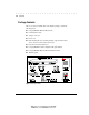
. . . . . . . . . . . . . . . . . . . . . . . . . . . . . . 1-3 Hub Components This section provides an overview of the Compaq HB1004 hub’s components including the LED indicators, RJ-45 ports, and the serial COM port. Figure 1-1 shows the hub’s front panel. Figure 1-1 Compaq HB1004 10Base-T Ethernet Hub Front Panel RJ-45 Ports The hub’s four RJ-45 ports allow connections to workstations and servers in a 10Base-T network via UTP cabling.
. . . . . . . . . . . . . . . . . . . . . . . . . . . . . . 1-4 Overview Unit LEDs The unit-level LEDs on the HB1004 indicate the status of the power supply and the percentage of use and collisions on the hub.
. . . . . . . . . . . . . . . . . . . . . . . . . . . . . . 1-5 Port LEDs There are two LEDs for each port to indicate link/activity and partition/disable on the ports.
. . . . . . . . . . . . . . . . . . . . . . . . . . . . . . 2-1 Chapter 2 Installation This chapter provides information to help you prepare for and install the hub and connect the hub to the network. Mounting the Hub You can place this hub directly on a desktop or mount it in a rack. Before you start installing the hub, make sure you can provide the right operating environment, including power requirements, sufficient physical space, and proximity to other network devices you want to connect.
. . . . . . . . . . . . . . . . . . . . . . . . . . . . . . 2-2 Installation Mounting the Hub in a Rack To mount the hub in a rack, follow these steps: 1. Use a standard EIA 19 inch rack 2. Use the brackets and screws supplied in the rack mounting kit 3. Use a cross-head screwdriver to attach the brackets to the side of the hub Figure 2-1 Attaching the Mounting Brackets 4.
. . . . . . . . . . . . . . . . . . . . . . . . . . . . . . 2-3 Connecting the Hub System The Compaq HB1004 hub has four RJ-45 ports, one of which serves as an MDI/MDI-X port. Making a Connection via an MDI-X Port You can connect any RJ-45 (MDI-X) station port on the hub to any device that uses a standard network interface such as a PC or server. You can also connect to an MDI-X port of a network interconnection device such as a bridge or router by using a cross-over cable. 1.
. . . . . . . . . . . . . . . . . . . . . . . . . . . . . . 2-4 Installation WARNING: Do not plug a phone jack connector into any RJ-45 port. This may damage the hub. Instead, use only twisted-pair cables with RJ-45 connectors. NOTES: 1. Make sure each twisted-pair cable does not exceed 100 meters (328 feet) 2. When using Port 4 as an MDI-X port, set the port selection switch to MDI-X Making a Connection via the MDI/MDI-X Port (Port 4) 1.
. . . . . . . . . . . . . . . . . . . . . . . . . . . . . . 2-5 I O Figure 2-4 Connecting the Power Cord 3. Check the LED marked PWR on the front panel to see if it is on. The unit will automatically select the setting that matches the connected input voltage. Therefore, no additional adjustments are necessary when connecting it to any input voltage within the specified range. See Appendix A for power requirements. 4. The hub performs a self-diagnostic test upon power-on.
. . . . . . . . . . . . . . . . . . . . . . . . . . . . . . 2-6 Installation Diagnostic Tests After power on, the hub automatically performs a diagnostic self-test. During this test, port status LEDs indicate the success or failure of each test. The system tests each component one at a time. At the completion of the test, if no diagnostic LEDs are lit, then all components passed the test. If a component fails the test, the corresponding LED will continue blinking.
. . . . . . . . . . . . . . . . . . . . . . . . . . . . . . 2-7 Verifying Hub and Port Status After the hub completes the POST, you can check hub activity and each connection by comparing the indicators with Table 2-2.
. . . . . . . . . . . . . . . . . . . . . . . . . . . . . . 2-8 Installation Applications This hub is not only designed to provide network access for 10Mb/s connections, but also to provide options in setting up network connections. It can be used as a simple stand-alone hub or can be cascaded to any compatible hub or switch. A sample configuration diagram is shown in Figure 2-7. Figure 2-7 A Sample Application Using the HB1004 10Base-T Ethernet Hub Writer: Weldon W.
. . . . . . . . . . . . . . . . . . . . . . . . . . . . . . 3-1 Chapter 3 Setup and Configuration Preparing for Configuration Management There are two methods for configuring the Compaq HB1004 - using the out-ofband program or using in-band network management software (not supplied). The diskette included with the Compaq HB1004 contains the menu-driven Compaq HB1004 System Configuration Program. To use this program, make a direct PC or modem connection to the serial port on the front of the hub.
. . . . . . . . . . . . . . . . . . . . . . . . . . . . . . 3-2 Setup and Configuration Figure 3-1. Out-of-Band Connection Using an Onsite PC Modem Connection Connect the COM port on the hub to the serial port on the modem. Use the communications cable provided with the hub and DB9/25 to RJ-45 converters as needed. At the remote site, connect the PC’s COM port to the remote modem. Configure the PC’s COM port and the modems for 9600 baud, 8 bits, no parity, and one stop bit (9600, 8, N, 1).
. . . . . . . . . . . . . . . . . . . . . . . . . . . . . . 3-3 In-Band Connection You can configure and manage the hub through the network (in-band) by using a network management application (not supplied). However, before you can access the hub with an in-band connection you must use an out-of-band connection and the Compaq HB1004 System Configuration Program to configure the hub’s IP address, subnet mask, and default gateway.
. . . . . . . . . . . . . . . . . . . . . . . . . . . . . . 3-4 Setup and Configuration To start the Compaq HB1004 System Configuration Program from Windows: 1. Insert the Compaq HB1004 Configuration Program diskette into the floppy disk drive 2. In File Manager or Program Manager, click File, then click Run 3. Type A:\HB1004CP for Drive A or B:\HB1004CP for Drive B in the Command Line box 4. Click the OK button to open the program and display the communication dialog box shown in Figure 3-3.
. . . . . . . . . . . . . . . . . . . . . . . . . . . . . . 3-5 NOTE: The Compaq HB1004 System Configuration Program allows selection of COM Ports 1, 2, 3 or 4 and assumes the normal default IRQ for the appropriate port (i.e. COM1 is IRQ4, COM2 is IRQ3, COM3 is IRQ4 and COM4 is IRQ3). If your communication port is configured differently, it is necessary to specify the correct IRQ for that port. If this is the case, type: A:\HB1004CP /i[irq#] or B:\HB1004CP /i[irq#] in the Open box.
. . . . . . . . . . . . . . . . . . . . . . . . . . . . . . 3-6 Setup and Configuration Figure 3-4 DCE/DTE Dialog Box 3. Select the appropriate option in the DCE/DTE dialog box: Q Terminal Channel for local hookup, opens the Main Menu as shown in Figure 3-6. Q Modem Channel for remote connection via modems. If you are using a modem connection, select Modem Channel to open the Phone List menu as shown in Figure 3-5. Enter the phone number and press to start the dialing mechanism.
. . . . . . . . . . . . . . . . . . . . . . . . . . . . . . 3-7 Once the connection is established, the Main Menu for out-of-band configuration appears as shown in Figure 3-6. Figure 3-6 Main Menu 4. Select any of the displayed menu items as described in the following section. Table 3-1 describes each of the Main Menu items. Compaq HB1004 System Configuration The Compaq HB1004 provides a proprietary, user-friendly, menu driven outof-band program (Compaq HB1004 System Configuration Program).
. . . . . . . . . . . . . . . . . . . . . . . . . . . . . .
. . . . . . . . . . . . . . . . . . . . . . . . . . . . . . 3-9 Table 3-2 Common Menu Key Functions Key Function F1 Help – Displays help for the current menu F2 Modify – Changes the value in a modifiable field F3 Set – Sets the menu field selections as the current settings (see System Configuration Settings) F6 Refresh – Refreshes the display in the menu ESC Exit – Exits the current menu and returns to the previous menu.
. . . . . . . . . . . . . . . . . . . . . . . . . . . . . . 3-10 Setup and Configuration The Factory Default configuration settings never change and are always available to apply to the hub. When you select Factory Setting from the Main Menu the Factory Default configuration is loaded into the Current configuration. See Table B-3 in Appendix B for a list of all factory default settings.
. . . . . . . . . . . . . . . . . . . . . . . . . . . . . . 3-11 Changing System Configuration Use the Configuration command from the Main Menu to modify current values for the following parameters: Figure 3-8. System Configuration Screen Parameter Description Q IP Address - IP address of the HB1004 agent. The agent runs the SNMP protocol over the UDP/IP transport protocol. In this environment, all systems on the Internet, such as network interconnection devices are assigned an IP address.
. . . . . . . . . . . . . . . . . . . . . . . . . . . . . . 3-12 Setup and Configuration Assigning Trap Managers Use the Trap Managers command from the Main Menu to modify current values for the following parameters: Figure 3-9. Q Q Trap Managers Screen SNMP Community Names - The community strings authorized for trap management access. All community strings used for IP Trap Managers must be listed in this table. Community Name - A community entry authorized for trap management access.
. . . . . . . . . . . . . . . . . . . . . . . . . . . . . . 3-13 Configuring Port Parameters Use the Port Control command to configure the ports. This menu provides a brief description of the hub, and also allows you to enable/disable any port on the hub. Figure 3-10. Port Control Screen Parameter Description Q Port Identifier - Numeric identifier 1 to 4. Q Name - User-defined name for selected port. Q Type - Connection type is 10BASE-T (RJ-45) Q Status - Any port may be ENABLED or DISABLED.
. . . . . . . . . . . . . . . . . . . . . . . . . . . . . . 3-14 Setup and Configuration Q Frames - Number of frames passing through this port or hub. Q Bytes - Number of bytes passing through this port or hub. Q Collisions - Number of simultaneous node transmissions detected by this port or hub. Q Alignment Errors - Number of mis-synchronized data packets detected by this port or hub. Q CRC Errors - Number of Ethernet Cyclic Redundancy Code errors detected by this port or hub.
. . . . . . . . . . . . . . . . . . . . . . . . . . . . . . 3-15 Q Retry - Number of attempts to make contact. Q Filename - The *.bin file to download. Q Transferred Block - Current number of data block being transferred. Q Total Blocks - Total number of blocks to transfer. Restarting the Agent Use the Restart command from the Main Menu to reset the agent. LEDs on the agent will light up sequentially as it executes the initialization test. This will also reset the statistics counter to 0 (zero).
. . . . . . . . . . . . . . . . . . . . . . . . . . . . . . A-1 Appendix A Specifications HB1004 10Base-T Ethernet Hub Q Access Method - CSMA/CD, 10 Mbps Q Standards Conformance - IEEE 802.3 10BASE-T Q Communication Rate - 10 Mbps Q Media Supported - 100Ω Category 3, 4, or 5 UTP/STP Q Number of Ports - 4 RJ-45 ports Q Indicator Panel LEDs for monitoring power, utilization, collisions, partition/disable, link/activity Q Dimensions - 440 x 171 x 43 mm (17.32 x 6.73 x 1.69 in) Q Weight - 2.
. . . . . . . . . . . . . . . . . . . . . . . . . . . . . . A-2 Specifications Network Criteria Q Hub-to-Workstation Distance 100 meters maximum using twisted-pair cable. Q Inter-hub Distance (MDI Port) 100 meters using twisted-pair cable (4 hub cascade). Q Total Network Span Single Hub 200 meters of twisted-pair cable (100 meters to each attached node). 4-hub Chain (MDI Port) 500 meters of twisted-pair cable (100 meters to each attached node and between hubs).
. . . . . . . . . . . . . . . . . . . . . . . . . . . . . . B-1 Appendix B Troubleshooting Diagnosing Hub Indicators The hub can be easily monitored through panel LED indicators to assist the network manager in identifying problems. This section describes common problems you may encounter and possible solutions.
. . . . . . . . . . . . . . . . . . . . . . . . . . . . . . B-2 Troubleshooting Power and Cooling Problems If the power indicator does not turn on when the power cord is plugged in, you may have a problem with the power outlet, power cord, or internal power supply as explained in the previous section.
. . . . . . . . . . . . . . . . . . . . . . . . . . . . . . B-3 Table B-2 RJ-45 Port Pin Assignments Pin Assignment (Hub Ports 1 – 4) Assignment (MDI/MDI-X Port, other Device) 1 Input Receive Data + Output Transmit Data + 2 Input Receive Data - Output Transmit Data - 3 Output Transmit Data + Input Receive Data + 6 Output Transmit Data - Input Receive Data - 4, 5, 7, 8 Not Used Not Used Twisted Pair Cable Figure B-1 shows the wiring for Straight-Through and Crossover twisted-pair cable.
. . . . . . . . . . . . . . . . . . . . . . . . . . . . . . B-4 Troubleshooting Using Diagnostic Mode When you power up the HB1004 hub, the unit executes a self-test. If the management agent fails the self-test the unit will not become active and the diagnostic LED will remain lit. Run the Compaq HB1004 System Configuration Program to open the Diagnostic Mode Main Menu. The Diagnostic Mode provides a limited set of tools to assist you in resolving the problem and getting the unit operational.
. . . . . . . . . . . . . . . . . . . . . . . . . . . . . . B-5 Download The Download option allows you to download software to the agent’s flash ROM. The Diagnostic Mode Download operation and screen is the same as for normal mode. See Chapter 3 “Downloading System Software” for information. Factory Settings This option allows you to reset all hub settings to the default factory configuration. The Diagnostic Mode Factory Settings operation and screen is the same as for normal mode.
. . . . . . . . . . . . . . . . . . . . . . . . . . . . . . B-6 Troubleshooting Help The Help option provides a brief description of the Diagnostic Mode Maim Menu options. Exit Exits the Diagnostic Mode and returns to DOS. Writer: Weldon W. Rowan Project: Troubleshooting Comments: File Name:SAB_B.
. . . . . . . . . . . . . . . . . . . . . . . . . . . . . . C-1 Appendix C Certification and Compliance European Union (EU) Notice Products with the CE Marking comply with both the EMC Directive (89/336/EEC) and the Low Voltage Directive (73/23/EEC) issued by the Commission of the European Community.
. . . . . . . . . . . . . . . . . . . . . . . . . . . . . . C-2 Certification and Compliance 7. Die Belüftungsöffnungen dienen der Luftzirkulation, die das Gerät vor Überhitzung schützt. Sorgen Sie dafür, daß diese Öffnungen nicht abgedeckt werden. 8. Beachten Sie beim Anschluß an das Stromnetz die Anschlußwerte. 9. Verlegen Sie die Netzanschlußleitung so, daß niemand darüber fallen kann. Es sollte auch nichts auf der Leitung abgestellt werden. 10.
. . . . . . . . . . . . . . . . . . . . . . . . . . . . . . I-1 H Index Hardware address 3-11 A I Access Management 3-12 Alignment Errors 3-14 IEEE 802.
. . . . . . . . . . . . . . . . . . . . . . . . . . . . . .