. . . . . . . . . . . . . . . . . . . . . . . . . . . . . .
. . . . . . . . . . . . . . . . . . . . . . . . . . . . . . NOTICE The information in this publication is subject to change without notice. COMPAQ COMPUTER CORPORATION SHALL NOT BE LIABLE FOR TECHNICAL OR EDITORIAL ERRORS OR OMISSIONS CONTAINED HEREIN, NOR FOR INCIDENTAL OR CONSEQUENTIAL DAMAGES RESULTING FROM THE FURNISHING, PERFORMANCE, OR USE OF THIS MATERIAL. This publication contains information protected by copyright.
. . . . . . . . . . . . . . . . . . . . . . . . . . . . . . iii Contents Chapter 1 Introduction Compaq Keyboard/Monitor/Mouse Switch Box Features ........................................1-1 Configurations ........................................................................................................1-2 Chapter 2 Installation Attaching the Slide Rail Brackets............................................................................2-1 Preparing the Rack-Mount Brackets ...........................
. . . . . . . . . . . . . . . . . . . . . . . . . . . . . . iv Displaying Version Information and Device Settings ..............................................3-4 Basic Switch Functions continued Saving the Hardware Configuration ........................................................................3-5 Resetting the Mouse and Keyboard .........................................................................3-5 Setting a Scanning Pattern...................................................................
. . . . . . . . . . . . . . . . . . . . . . . . . . . . . . v Appendix D Regulatory Notices Appendix E Power Cord Set Requirements General Requirements............................................................................................ E-1 Country-Specific Requirements.............................................................................. E-2 Index Compaq Keyboard/Monitor/Mouse Switch Box User Guide Writer: Kristi Wishon Project: Table of Contents Comments: File Name:C-toc.
. . . . . . . . . . . . . . . . . . . . . . . . . . . . . . 1-1 Chapter 1 Introduction The Compaq Keyboard/Monitor/Mouse Switch Box is a device that switches a single keyboard, mouse, and monitor between multiple Compaq computers. The Keyboard/Monitor/Mouse Switch Box is a space-efficient 1 U height (1.75-inch) device and is available in four- and eight-port models. This chapter provides an overview of the product features, functionality, and sample configurations.
. . . . . . . . . . . . . . . . . . . . . . . . . . . . . . 1-2 Introduction ■ External Keypad Jack - The Keyboard/Monitor/Mouse Switch Box has an external keypad jack to support rack-mounted Compaq products. In this configuration, the switch is mounted behind a door in a cabinet and the optional keypad is mounted outside the cabinet for easy access.
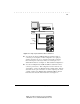
. . . . . . . . . . . . . . . . . . . . . . . . . . . . . . 1-3 Master Switch Keyboard, Mouse, and Video Cables HYDR-001.EPS Figure 1-1. Single Keyboard/Monitor/Mouse Switch Box ■ You can pair two Keyboard/Monitor/Mouse Switch Box units to connect up to 16 computers. In this configuration, two eight-port switches are placed one on top of another with a cable connecting them. This requires only 2U (3.5 inches) of vertical space. For additional information, see Chapter 4, “Paired Switch Configurations.
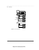
. . . . . . . . . . . . . . . . . . . . . . . . . . . . . . 1-4 Introduction Master Switch Keyboard, Mouse, and Video Cables HYDR-002.EPS Slave Switch Figure 1-2. Tiered Configuration Writer: Kristi Wishon Project: Introduction Comments: File Name:D-ch01.
. . . . . . . . . . . . . . . . . . . . . . . . . . . . . . 2-1 Chapter 2 Installation This chapter provides installation information for the Compaq Keyboard/Monitor/Mouse Switch Box. WARNING: To reduce the risk of personal injury or damage to the equipment be sure that; the leveling feet are extended to the floor and supporting the full weight of the rack. Each rack should be level and stable. Racks that are not coupled together require the installation of stabilizing feet.
. . . . . . . . . . . . . . . . . . . . . . . . . . . . . . 2-2 Installation HYDR-003.EPS Figure 2-1. Attaching slide rail brackets Preparing the Rack-Mount Brackets Prepare the rack-mount brackets for cable management in the rack by attaching the plastic cable ties. The cable ties snap into place, with the tie on the outside of the bracket. See Figure 2-2. After the cable ties are in place, install the rack-mount brackets in the rack by sliding the two back tabs in the back mounting rail.
. . . . . . . . . . . . . . . . . . . . . . . . . . . . . . 2-3 HYDR-010.EPS Figure 2-2. Snapping cable ties into place Rack-mount Installation Slide the Keyboard/Monitor/Mouse Switch Box into the rack-mount brackets until it snaps into place, as shown in Figure 2-3. HYDR-007.EPS Figure 2-3. Sliding the Keyboard/Monitor/Mouse Switch Box into rack-mount brackets Compaq Keyboard/Monitor/Mouse Switch Box User Guide Writer: Kristi Wishon Project: Installation Comments: File Name:E-ch02.
. . . . . . . . . . . . . . . . . . . . . . . . . . . . . . 2-4 Installation Cover Panel Installation After the unit is fully installed, secure the front cover panel using the middle hole, as shown below. HYDR-008.EPS Figure 2-4.
. . . . . . . . . . . . . . . . . . . . . . . . . . . . . . 2-5 Monitor Computer 3 Monitor Power Cord Connector HYDR-004.EPS Keyboard Mouse Computer 3 Computer 3 Power Keyboard Mouse Switch Figure 2-5. Keyboard/Monitor/Mouse Switch Box Connectors 2. Decide which computer is to be connected to port 1. Connect the computer’s keyboard and mouse to the jacks marked K and M, respectively, beneath the port labeled One. Connect the computer’s monitor to the 15-pin VGA connector.
. . . . . . . . . . . . . . . . . . . . . . . . . . . . . . 2-6 Installation WARNING: To reduce the risk of electric shock or damage to your equipment, do not disable the power cord grounding feature. This equipment is designed to be connected to a grounded (earthed) power outlet that is easily accessible to the operator. The grounding plug is an important safety feature. 4. Connect the power cord to the Keyboard/Monitor/Mouse Switch Box.
. . . . . . . . . . . . . . . . . . . . . . . . . . . . . . 2-7 Computer Startup Behavior During startup the computers send device settings to the Keyboard/Monitor/Mouse Switch Box. The unit then generates standard responses to these commands and allows the computers to boot successfully without actually being physically connected to the devices. Once you have the switch installed you can save these settings to non-volatile RAM (NVRAM). See Chapter 3 for additional information.
. . . . . . . . . . . . . . . . . . . . . . . . . . . . . . 2-8 Installation Whenever you switch between two computers, the Keyboard/Monitor/Mouse Switch Box reconfigures the keyboard and mouse using the settings stored in its memory. For example, if the current computer selected has Caps Lock turned On, but the user is switching to a second computer that has Caps Lock turned Off, then the unit turns Caps Lock Off to match the setting for the second computer.
. . . . . . . . . . . . . . . . . . . . . . . . . . . . . . 3-1 Chapter 3 Basic Switch Functions This chapter provides information on basic switch functions such as resetting the Keyboard/Monitor/Mouse Switch Box, connecting the keyboard and mouse while the system is powered up, and basic and advanced commands. Unit Operation Basic operation of the Keyboard/Monitor/Mouse Switch Box is achieved through the keyboard and a series of windows and menus that appear on the monitor.
. . . . . . . . . . . . . . . . . . . . . . . . . . . . . . 3-2 Basic Switch Functions Checking Port/Computer Status You can confirm which ports are currently active and whether each port has a computer or a slave switch connected by the following: 1. Press Print Scrn. The CCR Selection window appears on the monitor.
. . . . . . . . . . . . . . . . . . . . . . . . . . . . . .
. . . . . . . . . . . . . . . . . . . . . . . . . . . . . . 3-4 Basic Switch Functions Displaying Version Information and Device Settings To help when troubleshooting or supporting this system, the switch firmware version number can be displayed along with specific keyboard and mouse information for the currently selected computer. To show this information, proceed as follows: 1. Press Print Scrn. The CCR Selection window appears. 2. Press F2 and the Advanced Menu screen appears.
. . . . . . . . . . . . . . . . . . . . . . . . . . . . . . 3-5 The window contains keyboard information including enabled/disabled, typematic rate, LED settings, port mode and keyboard type. The mouse information includes enabled/disabled, sample rate, resolution, and mouse type. 4. Press Esc to remove the Version window.
. . . . . . . . . . . . . . . . . . . . . . . . . . . . . . 3-6 Basic Switch Functions 2. Press F2 and the Advanced Menu screen appears. The highlight is in the Commands menu. 3. Using the Up and Down arrow keys, move the highlight to Reset and press Enter. The mouse and keyboard are now reset. Setting a Scanning Pattern The unit defaults to a standard scan routine that sequentially connects each computer to the monitor, keyboard and mouse.
. . . . . . . . . . . . . . . . . . . . . . . . . . . . . . 3-7 7. When you have finished setting the scan pattern, press Enter. You can press Esc at any time prior to pressing enter to retain the previous scan pattern. Pressing the F2 key while in this screen, will return all Port and Sec values to factory defaults. 8. To exit CCR, press Esc. Assigning Names to Switch Ports In order to easily identify the computers connected to the switch, it is often helpful to assign unique names to each port.
. . . . . . . . . . . . . . . . . . . . . . . . . . . . . . 3-8 Basic Switch Functions Changing the Menu Attributes You can change the “look” or visual appearance of the Console Configuration Reporting (CCR) system menus to suit your own preferences.
. . . . . . . . . . . . . . . . . . . . . . . . . . . . . . 3-9 5. When you’ve completed all the desired changes, press Enter to save the changes to NVRAM. You can press Esc at any time prior to pressing Enter to cancel the operation and retain the previous settings. The following table describes each of the available menu attributes. Table 3-2 Menu Attributes Setting Effect on Menu/Window Appearance Resolution Affects the size of the menu and windows as they appear on the display.
. . . . . . . . . . . . . . . . . . . . . . . . . . . . . . 3-10 Basic Switch Functions Changing the Status Flag Attributes The status flag indicates the currently connected computer and can be set to appear on the screen whenever the system is operating.
. . . . . . . . . . . . . . . . . . . . . . . . . . . . . .
. . . . . . . . . . . . . . . . . . . . . . . . . . . . . . 3-12 Basic Switch Functions 2. Press F2 and the Advanced Menu screen appears. The highlight is in the Commands menu. Press the Right Arrow key to move the highlight to the Setup menu. 3. Using the Up and Down arrow keys, move the highlight to Devices and press Enter. The Device Setting window appears. 4.
. . . . . . . . . . . . . . . . . . . . . . . . . . . . . . 3-13 4. Enter the new password, and then press Enter. Passwords can be up to eight characters. This field is case sensitive. Then enter the new password again for confirmation, and press Enter. When entered correctly, the password field shows “CHANGED” to indicate that your new password has been accepted. 5. Wait time is the amount of time the system must be idle before the screen and keyboard lock is initiated.
. . . . . . . . . . . . . . . . . . . . . . . . . . . . . . 3-14 Basic Switch Functions You can also connect the mouse and/or keyboard to the switch while the system is powered up. When you connect a new device, the switch recognizes it, and configures it to the settings of the currently selected computer. This technique allows replacement of failed devices without having to restart the system.
. . . . . . . . . . . . . . . . . . . . . . . . . . . . . . 4-1 Chapter 4 Alternate Configurations There are other ways to configure your system, including paired switch configurations and tiered switch configurations. This chapter provides brief descriptions, installation instructions, and hardware requirements for these alternate configurations.
. . . . . . . . . . . . . . . . . . . . . . . . . . . . . . 4-2 Alternate Configurations Tiered Switch Configurations In tiered systems, you can connect additional switches to ports on a master unit. That is, switches can be tiered in master/slave configurations to allow one master switch to switch between computers or other switch units. Tiering simply involves linking the slave units’ physical keyboard, mouse, and monitor connections to one of the computer ports on the master unit.
. . . . . . . . . . . . . . . . . . . . . . . . . . . . . . 4-3 Connecting Tiers while the System is Powered Up If necessary, you can connect a master unit to a slave unit while the system is powered on. This technique can be used to isolate any problems with a minimum disruption to the system. When plugging a master Keyboard/Monitor/Mouse Switch Box into a slave unit, you must first connect the mouse and video cables, then connect the keyboard cable.
. . . . . . . . . . . . . . . . . . . . . . . . . . . . . . A-1 Appendix A Compaq Keyboard/Monitor/Mouse Switch Box Specifications Table A-1 Compaq Keyboard/Monitor/Mouse Switch Box Specifications Dimensions Height (1U = 1.75 inches) 1.75 in (4.5 cm) Depth 10.80 in (27.7 cm) Width 17.00 in (68.6 cm) Weight 9.1 lb (4.1 kg) Input Power Requirements Rated Voltage 100 -240 VAC Rated Frequency 50 - 60 Hz Rated Input Current 1.4 - 0.
. . . . . . . . . . . . . . . . . . . . . . . . . . . . . . A-2 Specifications Video Modes Supported VGA, SVGA, XGA Writer: Kristi Wishon Project: Specifications Comments: File Name:H-apa.
. . . . . . . . . . . . . . . . . . . . . . . . . . . . . . B-1 Appendix B Command Summary Table B-1 Keyboard Sequences for CCR (Console Configuration Reporting) Keyboard Entry PRINT SCRN Results Pressing once activates CCR. Pressing twice sends the print screen command to the selected computer.
. . . . . . . . . . . . . . . . . . . . . . . . . . . . . . B-2 Command Summary Writer: Kristi Wishon Project: Command Summary Comments: File Name:I-apb.
. . . . . . . . . . . . . . . . . . . . . . . . . . . . . . C-1 Appendix C Troubleshooting Tips Table C-1 System Troubleshooting Symptom No video on one computer No video or CCR on any computer Probable Cause Recommended Solution Loose video connection Reconnect video cable. Defective video cable Replace video cable. Computer powered down Power up the computer connected to that port. No power to unit Establish power connection.
. . . . . . . . . . . . . . . . . . . . . . . . . . . . . . C-2 Troubleshooting Tips Keyboard error on boot, one computer Loose keyboard connection Check that all cables are well seated. Ensure that mouse and keyboard cables are not swapped. Replace keyboard cable. Defective cable continued Writer: Kristi Wishon Project: Troubleshooting Tips Comments: File Name:J-apc.
Table C-1 continued Symptom Keyboard error on boot, all computers Probable Cause Loose keyboard connection Recommended Solution Check that all cables are well seated. Replace keyboard. Incompatible or defective keyboard Keyboard strokes shifted (swaps upper case for lower case) Computer left keyboard shifter state when last connected Press both SHIFT keys Mouse error on boot, one computer Loose mouse connection Check that all cables are well seated. Ensure that mouse/keyboard cables are not swapped.
. . . . . . . . . . . . . . . . . . . . . . . . . . . . . . C-4 Troubleshooting Tips Writer: Kristi Wishon Project: Troubleshooting Tips Comments: File Name:J-apc.
. . . . . . . . . . . . . . . . . . . . . . . . . . . . . . D-1 Appendix D Regulatory Notices Federal Communications Commission Notice Part 15 of the Federal Communications Commission (FCC) Rules and Regulations has established Radio Frequency (RF) emission limits to provide an interference-free radio frequency spectrum. Many electronic devices, including computers, generate RF energy incidental to their intended function and are, therefore, covered by these rules.
. . . . . . . . . . . . . . . . . . . . . . . . . . . . . . D-2 Regulatory Notices Class B Equipment This equipment has been tested and found to comply with the limits for a Class B digital device, pursuant to Part 15 of the FCC Rules. These limits are designed to provide reasonable protection against harmful interference in a residential installation.
. . . . . . . . . . . . . . . . . . . . . . . . . . . . . . D-3 European Union (EU) Notice Products with the CE Marking comply with both the EMC Directive (89/336/EEC) and the Low Voltage Directive (73/23/EEC) issued by the Commission of the European Community.
. . . . . . . . . . . . . . . . . . . . . . . . . . . . . . E-1 Appendix E Power Cord Set Requirements The voltage select switch feature of your switch box permits it to operate from any line voltage between 100-120 or 200-240 volts AC. The power cord set (appliance coupler, flexible cord, and wall plug) you received with your switch box meets the requirements for use in the country where you purchased your equipment.
. . . . . . . . . . . . . . . . . . . . . . . . . . . . . . E-2 Power Cord Set Requirements Country-Specific Requirements Use the following table to identify the appropriate accredited agency in your country.
. . . . . . . . . . . . . . . . . . . . . . . . . . . . . . E-3 Notes: 1. Flexible cord must be Type HO5VV-F, 3-conductor, 1.0 mm2 conductor size. Power cord set fittings (appliance coupler and wall plug) must bear the certification mark of the agency responsible for evaluation in the country where it will be used. 2. Flexible cord must be Type SV or equivalent, No. 18 AWG, 3-conductor. Wall plug must be a two-pole grounding type with a NEMA 5-15P (15A, 125V) or NEMA 6-15) (15A 250V) configuration.
. . . . . . . . . . . . . . . . . . . . . . . . . . . . . .
. . . . . . . . . . . . . . . . . . . . . . . . . . . . . .