HP Mini 210, HP Mini 110, Compaq Mini CQ10 Maintenance and Service Guide
© Copyright 2012 Hewlett-Packard Development Company, L.P. Bluetooth is a trademark owned by its proprietor and used by Hewlett-Packard Company under license. Intel and Atom are trademarks or registered trademarks of Intel Corporation in the United States and other countries. Microsoft and Windows are U.S. registered trademarks of Microsoft Corporation. SD Logo is a trademark of its proprietor. The information contained herein is subject to change without notice.
Safety warning notice WARNING! To reduce the possibility of heat-related injuries or of overheating the device, do not place the device directly on your lap or obstruct the device air vents. Use the device only on a hard, flat surface. Do not allow another hard surface, such as an adjoining optional printer, or a soft surface, such as pillows or rugs or clothing, to block airflow. Also, do not allow the AC adapter to contact the skin or a soft surface, such as pillows or rugs or clothing, during operation.
iv Safety warning notice
Table of contents 1 Product description ........................................................................................................... 1 2 External component identification ..................................................................................... 6 Keys ....................................................................................................................................... 6 Display ......................................................................................
Service tag ............................................................................................................. 48 Computer feet ......................................................................................................... 49 Battery ................................................................................................................... 50 SIM (select models only) ........................................................................................... 51 WLAN module .....
Using a Windows 7 operating system DVD (purchased separately) ............................... 98 8 Power cord set requirements ........................................................................................ 100 Requirements for all countries ................................................................................................ 100 Requirements for specific countries and regions ....................................................................... 101 9 Recycling ........................
viii
1 Product description Category Description HP Mini 210 Product Name HP Mini 210 √ HP Mini 110 √ HP Mini 110 √ Compaq Mini CQ10 Processors ● Intel® Atom N2800 1.86-GHz processor, dual core, 1.0-MB L2 cache, 1066-MHz front-side bus (FSB), 6.5 W ● Intel Atom N2600 1.60-GHz processor, dual core, 1.0-MB L2 cache, 800-MHz FSB, 3.
Category Description HP Mini 210 HP Mini 110 Compaq Mini CQ10 Memory One customer-accessible/upgradable memory module slot √ √ √ Supports 6.35-cm (2.5-in) hard drives in 9.5-mm (.37-in) and 7.0-mm (.
Category Description Wireless External media cards HP Mini 210 HP Mini 110 Compaq Mini CQ10 Integrated wireless local area network (WLAN) options by way of wireless module √ √ √ Two WLAN antennas built into display assembly √ √ √ Support for the following WLAN formats: √ √ √ Integrated wireless wide area network (WWAN) options by way of wireless module √ √ √ Two WWAN antennas built into display assembly √ √ √ Support for the following WLAN formats: √ √ √ √ √ √ ● Atheros 94
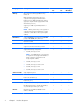
Category Description Ports ● 3-pin AC power ● Audio-in (mono microphone) ● Audio-out (stereo headphone) ● RJ-45 (Ethernet, includes link and activity lights) ● USB 2.0 (3 ports) ● VGA (Dsub 15 pin) supporting 1920 ×1200 external resolution @ 60Hz, hot plug and unplug and auto-detection for correct output to wide-aspect vs.
Category Description ● Serviceability HP Mini 210 Free DOS (does not support Beats Audio, EnergyStar 5.
2 External component identification Keys 6 Item Component Description (1) Action keys Execute frequently used system functions. (2) fn key Executes frequently used system functions when pressed in combination with a function key, the num lk key, or the esc key. (3) Windows logo key Displays the Windows Start menu. (4) Windows applications key Displays a shortcut menu for items beneath the pointer.
Display Item Component Description (1) WLAN antennas (2)* Send and receive wireless signals to communicate with WLANs. (2) WWAN antennas (2)* Send and receive wireless signals to communicate with WWANs. (3) Internal microphone Records sound. (4) Webcam Records video and captures still photographs. To use the webcam, double-click the ArcSoft Camera Suite icon on the desktop, or select Start > All Programs > ArcSoft Camera Suite > Launch WebCam Companion.
Buttons Item Component Description (1) Power button ● When the computer is off, press the button to turn on the computer. ● When the computer is on, press the button briefly to initiate Sleep. ● When the computer is in the Sleep state, press the button briefly to exit Sleep. ● When the computer is in Hibernation, press the button briefly to exit Hibernation.
Lights Item Component Description (1) Power light ● White: The computer is on. ● Blinking white: The computer is in the Sleep state. ● Off: The computer is off or in Hibernation. ● Amber: Computer sound is off. ● Off: Computer sound is on. ● White: An integrated wireless device, such as a WLAN device and/or a Bluetooth device, is on. ● Amber: All wireless devices are off. (2) (3) Mute light Wireless light (4) Caps lock light On: Caps lock is on.
TouchPad 10 Item Component Description (1) TouchPad light ● On: The TouchPad is on. ● Amber: The TouchPad is off. (2) TouchPad on/off button Quickly double-tap the TouchPad on/off button to turn the TouchPad off and on. (3) TouchPad zone Moves the pointer and selects or activates items on the screen. (4) Left TouchPad button Functions like the left button on an external mouse. (5) Right TouchPad button Functions like the right button on an external mouse.
Left side Item Component Description (1) External monitor port Connects an external VGA monitor or projector. (2) Power connector Connects an AC adapter. (3) AC adapter/battery light ● Amber: The computer is connected to external power, and the battery is charging. ● White: The computer is connected to external power, and the battery is fully charged. ● Blinking white: The computer is in the Sleep state, or the battery charge level is 10% or less (recharge the battery as soon as possible).
Right side Item Component Description (1) Digital Media Slot Supports the following digital card formats: ● MultiMediaCard ● Secure Digital (SD) Memory Card ● Secure Digital High Capacity (SDHC) Memory Card ● Secure Digital Extended Capacity (SDxC) Supports mini versions by use of an adapter (adapter is not included). (2) Audio-out (headphone) jack Produce sound when connected to optional powered stereo speakers, headphones, ear buds, a headset, or television audio.
Bottom Item Component Description (1) Battery bay Holds the battery and the subscriber identity module (SIM) slot. (2) Battery/service cover release latch Releases the battery from the battery bay and the service cover from the computer. (3) Service cover Provides access to the hard drive bay, the memory module slot, the WLAN module, and the WWAN module (select models only).
3 14 Illustrated parts catalog Chapter 3 Illustrated parts catalog
Service tag When ordering parts or requesting information, provide the computer serial number and model description provided on the service tag. Item Description Function (1) Product name This is the product name affixed to the front of the computer. (2) Serial number (s/n) This is an alphanumeric identifier that is unique to each product. (3) Part number/Product number (p/n) This number provides specific information about the product's hardware components.
Computer major components 16 Chapter 3 Illustrated parts catalog
Item Component (1) Display assembly, 10.
Item Component Spare part number Keyboard in black finish for use only on Compaq Mini CQ10 and HP Mini 110 computer models: For use in Belgium 658517-A41 For use in Bulgaria 658517-261 For use in Canada 658517-121 For use in the Czech Republic and Slovakia 658517-FL1 For use in Denmark, Finland, and Norway 658517-DH1 For use in France 658517-051 For use in Germany 658517-041 For use in Greece 658517-DJ1 For use in Hungary 658517-211 For use in Israel 658517-BB1 For use in Italy 65851
Item Component Spare part number For use in Denmark, Finland, and Norway 665962-DH1 For use in France 665962-051 For use in Germany 665962-041 For use in Greece 665962-DJ1 For use in Hungary 665962-211 For use in India 665962-D61 For use in Israel 665962-BB1 For use in Italy 665962-061 For use in Japan 665962-291 For use in Latin America 665962-161 For use in the Netherlands 665962-B31 For use in Portugal 665962-131 For use in Russia 665962-251 For use in Saudi Arabia 665962-17
Item Component Spare part number For use in Hungary 665965-211 For use in India 665965-D61 For use in Israel 665965-BB1 For use in Italy 665965-061 For use in Japan 665965-291 For use in Latin America 665965-161 For use in the Netherlands 665965-B31 For use in Portugal 665965-131 For use in Russia 665965-251 For use in Saudi Arabia 665965-171 For use in Slovenia 665965-BA1 For use in South Korea 665965-AD1 For use in Spain 665965-071 For use in Switzerland 665965-BG1 For use i
Item Component Spare part number For use in Japan 665964-291 For use in Latin America 665964-161 For use in the Netherlands 665964-B31 For use in Portugal 665964-131 For use in Russia 665964-251 For use in Saudi Arabia 665964-171 For use in Slovenia 665964-BA1 For use in South Korea 665964-AD1 For use in Spain 665964-071 For use in Switzerland 665964-BG1 For use in Taiwan 665964-AB1 For use in Thailand 665964-281 For use in Turkey 665964-141 For use in the United Kingdom and Sin
Item Component Spare part number For use in Russia 665963-251 For use in Saudi Arabia 665963-171 For use in Slovenia 665963-BA1 For use in South Korea 665963-AD1 For use in Spain 665963-071 For use in Switzerland 665963-BG1 For use in Taiwan 665963-AB1 For use in Thailand 665963-281 For use in Turkey 665963-141 For use in the United Kingdom and Singapore 665963-031 For use in the United States 665963-001 Keyboard in sweet purple finish for use only on HP Mini 210 computer models: 2
Item (3) Component Spare part number For use in Spain 665966-071 For use in Switzerland 665966-BG1 For use in Taiwan 665966-AB1 For use in Thailand 665966-281 For use in Turkey 665966-141 For use in the United Kingdom and Singapore 665966-031 For use in the United States 665966-001 Top cover (includes TouchPad board and bracket): In black finish for use only on Compaq Mini CQ10 and HP Mini 110 computer models 663677-001 In charcoal finish for use only on HP Mini 210 computer models 6507
Item Component Spare part number For use only with non-Beats Edition computer models equipped with an Intel Atom N2600 1.60-GHz processor, but not WWAN capability (1.0-MB L2 cache, dual core, 3.5 W) 676909-001 (6) Heat sink (includes replacement thermal material) 651898-001 (7) Fan 651897-001 (8) Power connector cable 656095-001 (9) Battery: (10) 646757-001 3-cell, 28-Wh, 2.
Item (17) Component Spare part number Service cover in crimson red finish for use only on HP Mini 210 computer models 650732-001 Service cover in luminous rose for use only on HP Mini 210 computer models 650731-001 Service cover in ocean drive for use only on HP Mini 210 computer models 650728-001 Service cover in sweet purple finish for use only on HP Mini 210 computer models 654203-001 Corner covers 652308-001 Rubber Kit (includes 2 rubber feet) 650734-001 Computer major components 25
Display assembly subcomponents 26 Item Component (1) Display bezel: Spare part number For use only on Compaq Mini CQ10 computer models 658504-001 For use only on HP Mini 110 computer models 658503-001 (2) Webcam/microphone module 658516-001 (3) 10.
Item Component Spare part number For use only on Compaq Mini CQ10 computer models 658518-001 In black finish for use only on HP Mini 110 computer models 658499-001 In Pacific blue finish for use only on HP Mini 110 computer models 658502-001 In Sonora red finish for use only on HP Mini 110 computer models 658500-001 Display assembly subcomponents 27
Mass storage devices Item Component Spare part number (1) Hard drive (2.5-in, 7.
Miscellaneous parts Component Spare part number 40-W HP Smart AC adapter (RC/V 2-wire) 624502-001 HP mobile optical wireless 2.4-GHz mouse 597587-001 HP protective mini sleeve: In charcoal finish 631188-001 In crimson red finish 628348-001 In luminous rose finish 628344-001 In ocean drive finish 628346-001 Power cord (3-pin, black, 1.
Sequential part number listing 30 Spare part number Description 490371-001 Power cord for use in North America (3-pin, black, 1.83-m) 490371-011 Power cord for use in Australia (3-pin, black, 1.83-m) 490371-021 Power cord for use in Europe (3-pin, black, 1.83-m) 490371-031 Power cord for use in the United Kingdom and Singapore (3-pin, black, 1.83-m) 490371-061 Power cord for use in Italy (3-pin, black, 1.83-m) 490371-081 Power cord for use in Denmark (3-pin, black, 1.
Spare part number Description 634932-001 500-GB, 5400-rpm, 7.0-mm hard drive (does not include hard drive bracket, hard drive connector cable, hard drive rubber isolators, or screws) NOTE: The hard drive bracket, hard drive connector cable, hard drive rubber isolators, and screws are included in the Hard Drive Hardware Kit, spare part number 664913-001. 645191-001 250-GB, 5400-rpm, 7.
32 Spare part number Description 651898-001 Heat sink (includes replacement thermal material) 652308-001 Corner covers (includes left and right corner covers) 654203-001 Service cover in sweet purple finish 654204-001 Top cover in sweet purple finish for use only on HP Mini 210 computer models (includes TouchPad board and bracket) 655795-001 Atheros 9485GN 802.11b/g/n 1×1 WiFi and 3012 Bluetooth 4.0 Combo Adapter 656095-001 Power connector cable 657325-001 Broadcom 4313GN 802.
Spare part number Description 658517-051 Keyboard in black finish for use only on Compaq Mini CQ10 and HP Mini 110 computer models in France (includes keyboard cable) 658517-061 Keyboard in black finish for use only on Compaq Mini CQ10 and HP Mini 110 computer models in Italy (includes keyboard cable) 658517-071 Keyboard in black finish for use only on Compaq Mini CQ10 and HP Mini 110 computer models in Spain (includes keyboard cable) 658517-121 Keyboard in black finish for use only on Compaq Mini
34 Spare part number Description 658517-D61 Keyboard in black finish for use only on Compaq Mini CQ10 and HP Mini 110 computer models in India (includes keyboard cable) 658517-DH1 Keyboard in black finish for use only on Compaq Mini CQ10 and HP Mini 110 computer models in Denmark, Finland, and Norway (includes keyboard cable) 658517-DJ1 Keyboard in black finish for use only on Compaq Mini CQ10 and HP Mini 110 computer models in Greece (includes keyboard cable) 658517-FL1 Keyboard in black finish f
Spare part number Description 665962-211 Keyboard in charcoal finish for use only on HP Mini 210 computer models in Hungary (includes keyboard cable) 665962-251 Keyboard in charcoal finish for use only on HP Mini 210 computer models in Russia (includes keyboard cable) 665962-261 Keyboard in charcoal finish for use only on HP Mini 210 computer models in Bulgaria (includes keyboard cable) 665962-281 Keyboard in charcoal finish for use only on HP Mini 210 computer models in Thailand (includes keyboard
36 Spare part number Description 665963-061 Keyboard in ocean drive finish for use only on HP Mini 210 computer models in Italy (includes keyboard cable) 665963-071 Keyboard in ocean drive finish for use only on HP Mini 210 computer models in Spain (includes keyboard cable) 665963-121 Keyboard in ocean drive finish for use only on HP Mini 210 computer models in Canada (includes keyboard cable) 665963-131 Keyboard in ocean drive finish for use only on HP Mini 210 computer models in Portugal (includ
Spare part number Description 665963-DH1 Keyboard in ocean drive finish for use only on HP Mini 210 computer models in Denmark, Finland, and Norway (includes keyboard cable) 665963-DJ1 Keyboard in ocean drive finish for use only on HP Mini 210 computer models in Greece (includes keyboard cable) 665963-FL1 Keyboard in ocean drive finish for use only on HP Mini 210 computer models in the Czech Republic and Slovakia (includes keyboard cable) 665964-001 Keyboard in luminous rose finish for use only on
38 Spare part number Description 665964-AB1 Keyboard in luminous rose finish for use only on HP Mini 210 computer models in Taiwan (includes keyboard cable) 665964-AD1 Keyboard in luminous rose for use only on HP Mini 210 computer models in South Korea (includes keyboard cable) 665964-B31 Keyboard in luminous rose finish for use only on HP Mini 210 computer models in the Netherlands (includes keyboard cable) 665964-BA1 Keyboard in luminous rose finish for use only on HP Mini 210 computer models in
Spare part number Description 665965-171 Keyboard in crimson rose finish for use only on HP Mini 210 computer models in Saudi Arabia (includes keyboard cable) 665965-211 Keyboard in crimson rose finish for use only on HP Mini 210 computer models in Hungary (includes keyboard cable) 665965-251 Keyboard in crimson rose finish for use only on HP Mini 210 computer models in Russia (includes keyboard cable) 665965-261 Keyboard in crimson rose finish for use only on HP Mini 210 computer models in Bulgari
40 Spare part number Description 665966-051 Keyboard in sweet purple finish for use only on HP Mini 210 computer models in France (includes keyboard cable) 665966-061 Keyboard in sweet purple finish for use only on HP Mini 210 computer models in Italy (includes keyboard cable) 665966-071 Keyboard in sweet purple finish for use only on HP Mini 210 computer models in Spain (includes keyboard cable) 665966-121 Keyboard in sweet purple finish for use only on HP Mini 210 computer models in Canada (incl
Spare part number Description 665966-D61 Keyboard in sweet purple finish for use only on HP Mini 210 computer models in India (includes keyboard cable) 665966-DH1 Keyboard in sweet purple finish for use only on HP Mini 210 computer models in Denmark, Finland, and Norway (includes keyboard cable) 665966-DJ1 Keyboard in sweet purple finish for use only on HP Mini 210 computer models in Greece (includes keyboard cable) 665966-FL1 Keyboard in sweet purple finish for use only on HP Mini 210 computer mod
42 Spare part number Description 668164-001 10.1-in, WSVGA, HD display assembly in crimson red finish for use only on HP Mini 210 computer models (includes display panel cable, webcamera/microphone module, and WLAN antenna cables and transceivers) 668165-001 10.1-in, WSVGA, HD display assembly in sweet purple finish for use only on HP Mini 210 computer models (includes display panel cable, webcamera/microphone module, and WLAN antenna cables and transceivers) 668166-001 10.
4 Removal and replacement procedures Preliminary replacement requirements Tools required You will need the following tools to complete the removal and replacement procedures: ● Flat-bladed screwdriver ● Magnetic screwdriver ● Phillips P0 and P1 screwdrivers Service considerations The following sections include some of the considerations that you must keep in mind during disassembly and assembly procedures.
Drive handling CAUTION: Drives are fragile components that must be handled with care. To prevent damage to the computer, damage to a drive, or loss of information, observe these precautions: Before removing or inserting a hard drive, shut down the computer. If you are unsure whether the computer is off or in Hibernation, turn the computer on, and then shut it down through the operating system. Before handling a drive, be sure that you are discharged of static electricity.
CAUTION: To prevent damage to the computer when you are removing or installing internal components, observe these precautions: Keep components in their electrostatic-safe containers until you are ready to install them. Before touching an electronic component, discharge static electricity by using the guidelines described in this section. Avoid touching pins, leads, and circuitry. Handle electronic components as little as possible. If you remove a component, place it in an electrostatic-safe container.
Packaging and transporting guidelines Follow these grounding guidelines when packaging and transporting equipment: ● To avoid hand contact, transport products in static-safe tubes, bags, or boxes. ● Protect ESD-sensitive parts and assemblies with conductive or approved containers or packaging. ● Keep ESD-sensitive parts in their containers until the parts arrive at static-free workstations. ● Place items on a grounded surface before removing items from their containers.
Equipment guidelines Grounding equipment must include either a wrist strap or a foot strap at a grounded workstation. ● When seated, wear a wrist strap connected to a grounded system. Wrist straps are flexible straps with a minimum of one megohm ±10% resistance in the ground cords. To provide proper ground, wear a strap snugly against the skin at all times. On grounded mats with banana-plug connectors, use alligator clips to connect a wrist strap.
Component replacement procedures This chapter provides removal and replacement procedures. There are as many as 41 screws that must be removed, replaced, or loosened when servicing the computer. Make special note of each screw size and location during removal and replacement. Service tag When ordering parts or requesting information, provide the computer serial number and model number provided on the service tag. It is necessary to remove the battery to obtain these numbers.
Item Component Description (4) Warranty period This number describes the duration of the warranty period for the computer. (5) Model description This is the alphanumeric identifier used to locate documents, drivers, and support for the computer. Computer feet The computer feet are adhesive-backed rubber pads. There are 2 rubber feet that attach to the corner covers in the locations illustrated below. These rubber feet are available in the Rubber Kit, spare part number 650734-001.
Battery Description Spare part number 6-cell, 55-Wh, 2.55-Ah, Li-ion battery 646757-001 3-cell, 28-Wh, 2.55-Ah, Li-ion battery 646755-001 Before disassembling the computer, follow these steps: 1. Shut down the computer. If you are unsure whether the computer is off or in Hibernation, turn the computer on, and then shut it down through the operating system. 2. Disconnect all external devices connected to the computer. 3.
SIM (select models only) NOTE: The SIM is provided by the end-user as a security measure for the WWAN module. The SIM should be removed, placed into a static-dissipative container, and then replaced when the computer is reassembled. Before removing the SIM, follow these steps: 1. Shut down the computer. If you are unsure whether the computer is off or in Hibernation, turn the computer on, and then shut it down through the operating system. 2. Disconnect all external devices connected to the computer. 3.
WLAN module Description Spare part number Atheros 9485GN 802.11b/g/n 1×1 WiFi and 3012 Bluetooth 4.0 Combo Adapter 655795-001 Broadcom 4313GN 802.11b/g/n 1×1 WiFi and 20702 Bluetooth 4.0 Combo Adapter 657325-001 Intel Centrino Advanced-N 6230 WLAN module 631956-001 Ralink 5390GN 802.
The service cover is available using the following spare part numbers: 3.
5. Remove the WLAN module by pulling the module away from the slot at an angle (3). NOTE: The WLAN module is designed with a notch (4) to prevent incorrect installation into the WLAN module socket. NOTE: If the WLAN antennas are not connected to the terminals on the WLAN module, the protective sleeves must be installed on the antenna connectors, as shown in the following illustration. Reverse this procedure to install the WLAN module.
WWAN module Description Spare part number HP hs2340 HSPA+ Mobile Broadband Module 632155-001 HP lc2000 HSPA Mobile Broadband Module 612599-001 HP lc2010 HSPA Mobile Broadband Module 612600-001 CAUTION: To prevent an unresponsive system, replace the wireless module only with a wireless module authorized for use in the computer by the governmental agency that regulates wireless devices in your country or region.
3. Remove the WWAN module by pulling the module away from the slot at an angle (3). NOTE: The WWAN module is designed with a notch (4) to prevent incorrect installation into the WWAN module socket. NOTE: If the WWAN antennas are not connected to the terminals on the WWAN module, the protective sleeves must be installed on the antenna connectors, as shown in the following illustration. Reverse this procedure to install the WWAN module.
Memory module Description Spare part number 2-GB (PC3, 10600, 1333-MHz) 621565-001 Before removing the memory module, follow these steps: 1. Shut down the computer. If you are unsure whether the computer is off or in Hibernation, turn the computer on, and then shut it down through the operating system. 2. Disconnect all external devices connected to the computer. 3.
RTC battery Description Spare part number RTC battery 621565-001 Before removing the RTC battery, follow these steps: 1. Shut down the computer. If you are unsure whether the computer is off or in Hibernation, turn the computer on, and then shut it down through the operating system. 2. Disconnect all external devices connected to the computer. 3. Disconnect the power from the computer by first unplugging the power cord from the AC outlet and then unplugging the AC adapter from the computer. 4.
Hard drive NOTE: The hard drive spare part kit does not include the hard drive bracket, connector cable, rubber isolators, or screws. These components are included in the Hard Drive Hardware Kit, spare part number 664913-001. Description Spare part number 500-GB, 5400-rpm 634932-001 320-GB, 5400-rpm 645193-001 250-GB, 5400-rpm 645191-001 Before removing the hard drive, follow these steps: 1. Shut down the computer.
4. Remove the hard drive (4) by sliding it up and to the left at an angle. 5. If it is necessary to replace the hard drive connector cable (1), the hard drive screws (2), the hard drive bracket (3), or the rubber isolators (4), remove and replace the components. Reverse this procedure to reassemble and install the hard drive.
Keyboard NOTE: The keyboard spare part kit includes a keyboard cable.
62 Description Spare part number Description Spare part number For use in Italy 665962-061 For use in the United Kingdom and Singapore 665962-031 For use in Japan 665962-291 For use in the United States 665962-001 Keyboard in crimson red finish for use only on HP Mini 210 computer models: For use in Latin America 665965-161 For use in Belgium 665965-A41 For use in the Netherlands 665965-B31 For use in Bulgaria 665965-261 For use in Portugal 665965-131 For use in Canada 665965-121 F
Description Spare part number Description Spare part number For use in Italy 665964-061 For use in the United Kingdom and Singapore 665964-031 For use in Japan 665964-291 For use in the United States 665964-001 Keyboard in ocean drive finish for use only on HP Mini 210 computer models: For use in Latin America 665963-291 For use in Belgium 665963-A41 For use in the Netherlands 665963-161 For use in Bulgaria 665963-261 For use in Portugal 665963-B31 For use in Canada 665963-121 For u
Description Spare part number Description Spare part number For use in Italy 665966-061 For use in the United Kingdom and Singapore 665966-031 For use in Japan 665966-291 For use in the United States 665966-001 Before removing the keyboard, follow these steps: 1. Shut down the computer. If you are unsure whether the computer is off or in Hibernation, turn the computer on, and then shut it down through the operating system. 2. Disconnect all external devices connected to the computer. 3.
4. Insert a screw driver or similar thin tool into the keyboard release area, and then press on the back of the keyboard until the keyboard disengages from the computer. 5. Turn the computer right-side up with the front toward you. 6. Open the computer as far as it will open.
7. Lift the rear edge of the keyboard (1), and then swing the keyboard (2) up and forward until it rests upside down on the palm rest. 8. Release the zero insertion force (ZIF) connector (1) to which the keyboard cable is attached, and then disconnect the keyboard cable (2) from the system board. 9. Remove the keyboard (3). Reverse this procedure to install the keyboard.
Top cover NOTE: The top cover spare part kit includes the TouchPad and TouchPad cable.
3. Release the ZIF connector (1) to which the TouchPad cable is connected, and then disconnect the TouchPad cable (2) from the system board. NOTE: Additional slight force may be needed when releasing the TouchPad cable from the top cover. Double-sided adhesive is used to attach the TouchPad cable to the top cover surface. 4. 68 Remove the two rubber feet (1) on the rear corners of the base enclosure. (The rubber feet are available in the Rubber Kit, spare part number 650734-001.
5. Remove the seven Phillips PM2.0×5.0 screws (2) that secure the top cover and the corner covers to the base enclosure. NOTE: The rubber feet are notched differently. The rubber foot (1) that fits on the left side has a rectangular alignment notch. The rubber foot (2) that fits on the right side has an “L”-shaped alignment notch. When installing the rubber feet, align them according to the side of the computer on which they should be installed.
70 6. Remove the corner covers. 7. Release the wireless antenna cables from the clips (1) and routing channel built into the base enclosure. 8. Disconnect the display panel cable (2) from the system board.
9. Remove the two Phillips PM2.0×5.0 screws that secure the top cover to the base enclosure. 10. Turn the computer right side up, with the front toward you. 11. Open the computer as far as it will open. 12. Release the ZIF connector (1) to which the power button board cable is connected, and then disconnect the power button board cable (2) from the system board. 13. Disconnect the speaker cable (3) from the system board.
14. Remove the five Phillips PM2.0×5.0 screws that secure the top cover to the base enclosure. 15. Lift the front edge of the top cover (1) until the left and right sides disengage from the base enclosure. 16. Remove the top cover (2). Reverse this procedure to install the top cover.
Speakers Description Spare part number Speakers (include cable) 650736-001 Before removing the speakers, follow these steps: 1. Shut down the computer. If you are unsure whether the computer is off or in Hibernation, turn the computer on, and then shut it down through the operating system. 2. Disconnect all external devices connected to the computer. 3. Disconnect the power from the computer by first unplugging the power cord from the AC outlet and then unplugging the AC adapter from the computer.
System board NOTE: The system board spare part kit includes replacement thermal material. Description Spare part number For use only with Beats Edition computer models equipped with an Intel Atom N2800 1.86-GHz processor and WWAN capability (1.0-MB L2 cache, dual core, 6.5 W) 667753-001 For use only with non-Beats Edition computer models equipped with an Intel Atom N2800 1.86GHz processor and WWAN capability (1.0-MB L2 cache, dual core, 6.
● WWAN module (see WWAN module on page 55) ● RTC battery (see RTC battery on page 58) ● Memory module (see Memory module on page 57) ● Power connector cable (see System board on page 74) ● Fan (see Fan on page 77) ● Heat sink (see Heat sink on page 79) Remove the system board: 1. Remove the two Phillips PM2.0×5.7 screws that secure the system board to the base enclosure. 2. Release the power connector (1) from the clip built into the base enclosure. 3.
5. Remove the system board (4) by sliding it up and to the right at an angle. NOTE: If it is necessary to replace the power connector cable, turn the system board upside down with the rear toward you, and then disconnect the power connector cable from the system board. The power connector cable is available using spare part number 656095-001. Reverse this procedure to install the system board and the power connector cable.
Fan Description Spare part number Fan 651897-001 NOTE: To properly ventilate the computer, allow at least 7.6 cm (3 in) of clearance on the left side of the computer. The computer uses an electric fan for ventilation. The fan is controlled by a temperature sensor and is designed to turn on automatically when high temperature conditions exist.
5. 78 Remove the fan (4).
Heat sink Description Spare part number Heat sink (includes replacement thermal material) 651898-001 Before removing the heat sink, follow these steps: 1. Shut down the computer. If you are unsure whether the computer is off or in Hibernation, turn the computer on, and then shut it down through the operating system. 2. Disconnect all external devices connected to the computer. 3.
2. Remove the heat sink (2). NOTE: Due to the adhesive quality of the thermal material located between the heat sink and system board components, it may be necessary to move the heat sink from side to side to detach it. The thermal material must be thoroughly cleaned from the surfaces of the heat sink and the system board components each time the heat sink is removed. Replacement thermal material is included with the heat sink and system board spare part kits.
Display assembly Description Spare part number Display assembly 10.
3. Disconnect the power from the computer by first unplugging the power cord from the AC outlet and then unplugging the AC adapter from the computer. 4. Remove the battery (see Battery on page 50), and then remove the following components: ● Service cover (see WLAN module on page 52) ● Keyboard (see Keyboard on page 61) ● Top cover (see Top cover on page 67) Remove the display assembly: 1. Position the computer upside down, with the front toward you.
b. 5. Remove the display bezel (4). The display bezel is available using the following spare part numbers: ● 658504-001 — For use only on Compaq Mini CQ10 computer models ● 658503-001 — For use only on HP Mini 110 computer models If it is necessary to replace the webcamera/microphone module: a. Detach and release the module (1) as far as the module cable allows. (The module is attached to the display enclosure with double-sided tape.) b. Disconnect the module cable (2) from the module. c.
6. 7. 84 If it is necessary to replace the display panel: a. Remove the six Phillips PM2.0×4.6 screws (1) that secure the display panel to the display enclosure. b. Lift the top edge of the display panel (2) and swing it up and forward until it rests at an angle. c. Remove the display panel. The display panel is available using spare part number 658511-001. If it is necessary to replace the display hinges: a. Remove the four Phillips PM2.0×3.
8. If it is necessary to replace the display panel cable: CAUTION: Make sure the work surface is free of any foreign objects before turning the display panel upside down. Failure to clear the work surface can result in scratches and damage to the display panel surface. 9. a. Turn the display panel upside down with the bottom edge toward you. b. Release the tabs (1) built into the shielding on the back of the display panel that conceal the display panel connector and secure the display panel cable. c.
b. Release the wireless antenna cables from the clips (3) built into the display enclosure. c. Remove the wireless antenna cables and transceivers. The wireless antenna cables and transceivers are available in the Antenna Kit, spare part number 658498-001. Reverse this procedure to reassemble and install the display assembly.
5 Setup Utility (BIOS) and System Diagnostics Using Setup Utility Setup Utility, or Basic Input/Output System (BIOS), controls communication between all the input and output devices on the system (such as disk drives, display, keyboard, mouse, and printer). Setup Utility includes settings for the types of peripherals installed, the startup sequence of the computer, and the amount of system and extended memory. NOTE: Use extreme care when making changes in Setup Utility.
Navigating and selecting in Setup Utility To navigate and select in Setup Utility, follow these steps: 1. 2. Turn on or restart the computer, and then press esc while the “Press the ESC key for Startup Menu” message is displayed at the bottom of the screen. ● To select a menu or a menu item, use the tab key and the keyboard arrow keys and then press enter, or use a pointing device to click the item.
Restoring factory settings in Setup Utility NOTE: Restoring defaults will not change the hard drive mode. To return all settings in Setup Utility to the values that were set at the factory, follow these steps: 1. Turn on or restart the computer, and then press esc while the “Press the ESC key for Startup Menu” message is displayed at the bottom of the screen. 2. Press f10 to enter Setup Utility. 3. Use the arrow keys to select Exit > Load Setup Defaults. 4. Follow the on-screen instructions. 5.
Determining the BIOS version To determine whether available BIOS updates contain later BIOS versions than those currently installed on the computer, you need to know the version of the system BIOS currently installed. BIOS version information (also known as ROM date and System BIOS) can be displayed by pressing fn +esc (if you are already in Windows) or by using Setup Utility. 1. Start Setup Utility (BIOS). 2. Use the arrow keys to select Main. 3.
BIOS installation procedures vary. Follow any instructions that are displayed on the screen after the download is complete. If no instructions are displayed, follow these steps: 1. Windows 7—Open Windows Explorer by selecting Start > Computer. Windows XP—Open Windows Explorer by selecting Start > My Computer. 2. Double-click your hard drive designation. The hard drive designation is typically Local Disk (C:). 3.
6 Specifications Computer specifications Metric U.S. Width 26.8 cm 10.55 in Depth 19.1 cm 7.52 in Height (front to back) 2.3 to 3.3 cm 0.91 to 1.29 in Weight 1.26 kg (with 3-cell battery), 1.40 kg (with 6-cell battery) 2.77 lb (with 3-cell battery), 3.09 lb (with 6-cell battery) Dimensions Input power Operating voltage and current 19.5 V dc @ 2.
10.1-inch WSVGA display specifications Metric U.S. Height 23.5 cm 9.3 in Width 14.3 cm 5.6 in Diagonal 25.7 cm 10.1 in Number of colors 262,144 Contrast ratio 500:1 (typical) Brightness 200 nits (typical) Dimensions Pixel resolution Pitch 0.2175 × 0.2088 mm Format 1024 × 600 Configuration RGB vertical stripe Backlight LED Character display 80 × 25 Total power consumption 3.46 W Viewing angle ±45° horizontal, +15/–35° vertical (typical) 10.
Hard drive specifications 500-GB* 320-GB* 250-GB* Height 9.5 mm 9.5 and 7.0 mm 9.5 and 7.
7 Backup and recovery To protect your information, use Windows Backup and Restore to back up individual files and folders, back up your entire hard drive (select models only), create system repair discs (select models only) by using the installed optical drive (select models only) or an optional external optical drive, or create system restore points. In case of system failure, you can use the backup files to restore the contents of your computer.
Backing up your information Recovery after a system failure is as good as your most recent backup. You should create system repair discs (select models only) by using the installed optical drive (select models only) or an optional external optical drive, and your initial backup immediately after software setup. As you add new software and data files, you should continue to back up your system on a regular basis to maintain a reasonably current backup.
Performing a system recovery In case of system failure or instability, the computer provides the following tools to recover your files: ● Windows recovery tools: You can use Windows Backup and Restore to recover information you have previously backed up. You can also use Windows Startup Repair to fix problems that might prevent Windows from starting correctly. ● f11 recovery tools: You can use the f11 recovery tools to recover your original hard drive image.
NOTE: For additional information on recovering information using the Windows tools, perform a search for these topics in Help and Support. Using f11 recovery tools CAUTION: Using f11 completely erases hard drive contents and reformats the hard drive. All files you have created and any software installed on the computer are permanently removed. The f11 recovery tool reinstalls the operating system and HP programs and drivers that were installed at the factory.
5. Click Next. 6. Select Repair your computer. 7. Follow the on-screen instructions. After the repair is completed: 1. Eject the Windows 7 operating system DVD, and then insert the Driver Recovery disc. 2. Install the Hardware Enabling Drivers first, and then install Recommended Applications.
8 Power cord set requirements The wide-range input feature of the computer permits it to operate from any line voltage from 100 to 120 volts AC, or from 220 to 240 volts AC. The 3-conductor power cord set included with the computer meets the requirements for use in the country or region where the equipment is purchased. Power cord sets for use in other countries and regions must meet the requirements of the country or region where the computer is used.
Requirements for specific countries and regions Country/region Accredited agency Applicable note number Argentina IRAM 1 Australia SAA 1 Austria OVE 1 Belgium CEBEC 1 Brazil ABNT 1 Canada CSA 2 Chile IMQ 1 Denmark DEMKO 1 Finland FIMKO 1 France UTE 1 Germany VDE 1 India ISI 1 Israel SII 1 Italy IMQ 1 Japan JIS 3 The Netherlands KEMA 1 New Zealand SANZ 1 Norway NEMKO 1 The People's Republic of China CCC 4 Saudi Arabia SASO 7 Singapore PSB 1 So
102 Country/region Accredited agency Applicable note number The United States UL 2 1. The flexible cord must be Type HO5VV-F, 3-conductor, 0.75-mm² conductor size. Power cord set fittings (appliance coupler and wall plug) must bear the certification mark of the agency responsible for evaluation in the country or region where it will be used. 2. The flexible cord must be Type SVT/SJT or equivalent, No. 18 AWG, 3-conductor.
9 Recycling When a non-rechargeable or rechargeable battery has reached the end of its useful life, do not dispose of the battery in general household waste. Follow the local laws and regulations in your area for battery disposal. HP encourages customers to recycle used electronic hardware, HP original print cartridges, and rechargeable batteries. For more information about recycling programs, see the HP Web site at http://www.hp.com/recycle.
Index A AC adapter, spare part number 29, 30 AC adapter/battery light 11 Action keys 6 antenna locations 7 removal 85 spare part number 26, 32, 86 Antenna Kit, spare part number 26, 32, 86 audio, product description 2 audio-in jack 12 audio-out jack 12 B base enclosure, spare part numbers 24, 31, 34 battery removal 50 spare part numbers 24, 31, 50 battery bay 13 battery/service cover release latch 13 bottom components 13 button components 8 buttons power 8 TouchPad 10 TouchPad on/off 10 Web browser 8 C cab
removal 59 spare part numbers 24, 28, 31, 59 specifications 94 hard drive bracket illustrated 28 removal 60 hard drive connector cable illustrated 28 removal 60 Hard Drive Hardware Kit, spare part number 24, 28, 34, 59 hard drive light 11 hard drive rubber isolator illustrated 28 removal 60 headphone jack 12 heat sink removal 79 spare part number 24, 32, 79 hinge removal 84 spare part number 26, 84 J jacks audio-in 12 audio-out 12 headphone 12 microphone 12 network 12 RJ-45 12 K key components 6 keyboard pr
security cable slot 12 security, product description 4 serial number 48 service considerations cables 43 connectors 43 plastic parts 43 service cover location 13 removal 52 spare part numbers 24, 31, 32, 34, 53 service tag 15, 48 serviceability, product description 5 SIM, removal 51 sleeve, spare part numbers 29, 30 speakers removal 73 spare part number 23, 31, 73 specifications computer 92 display 93 hard drive 94 system board removal 74 spare part numbers 23, 41, 42, 74 T tools required 43 top cover remov