
User guide


Installing the Upgrade Module and Adapter 2-5
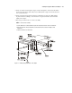
Connecting the Network Cable
Network connections for the adapter and upgrade modules use UTP or fiber cable. See the
sections “UTP Cable Specifications” and “Fiber Cable Specifications” in Appendix C for a
description of each upgrade module and the cable and mode each module supports.
Connecting UTP Network Cable
The ports on the NC3134 adapter and the NC3135 10/100 and NC7132 upgrade modules use the
following UTP connectors.
Table 2-1
UTP Network Cable Types
Network Type Connector
10BASE-T network Category 3, 4 or 5 twisted-pair cable
100BASE-TX network Category 5 twisted-pair cable connected to a 100BASE-TX hub or
switch
1000BASE-T network Category 5 (or better) twisted-pair cable connected to a
1000BASE-T hub or switch. This includes existing Gigabit over
copper connections. For new Gigabit over copper installations,
Category 5e – enhanced Category 5 -- is recommended.
Note: If you use the adapter in a residential environment, you must use a Category 5 (or better) cable for both
10BASE-T and 100BASE-TX networks.
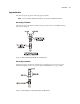
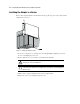
The UTP network connections on the adapter and upgrade modules are RJ-45 connectors. To
attach the cable, plug the cable connector into the port. When inserting an RJ-45 plug, ensure
that the tab on the plug clicks into position indicating that it is properly seated.
Connecting Fiber Network Cable
The NC3133, NC6132, and NC6133 fiber upgrade modules use SC fiber ports. These ports
support fiber with a maximum cable length dependent on the fiber type, mode, and cable size.
See Appendix C for fiber cable specifications.
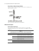
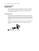
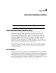
To insert the network SC connector into the port of the upgrade module, line up the slot on the
fiber connector with the key on the upgrade module and push gently until the retainers click into
place.
Figure 2-3. Inserting an SC fiber plug