Octal V.35 - Quad 10/100 RIOP Installation Guide Compatible Systems Corporation 4730 Walnut Street Suite 102 Boulder, Colorado 80301 303-444-9532 800-356-0283 http://www.compatible.
Octal V.35-Quad 10/100 RIOP Installation Guide, Version 1.0 Copyright© 1999, Compatible Systems Corporation All rights reserved. VSR, VSR-2, MicroRouter and CompatiView are trademarks of Compatible Systems Corporation. Other trademarks are the property of their respective holders. FCC Notice: This product has been certified to comply with the limits for a Class A computing device, pursuant to Subpart J of Part 15 of FCC Rules.
Table of Contents Introduction to the Octal V.35-Quad 10/100 RIOP 1 Chapter 1 - Network Installation 2 Connecting the Octal V.35-Quad 10/100 to the Ethernet Telco Line Connection Requirements Connecting a Line Device to the V.
Table of Contents IP Protocol SMDS Configuration Link Configuration SMDS Addressing SAVING A CONFIGURATION FILE TO FLASH ROM 9 9 9 10 10 10 10 10 10 10 10 11 11 11 11 Chapter 3 - Shipping Defaults 12 Required for IP Numbered Interface Suggested for IP IPX Protocol Required for IPX Suggested for IPX AppleTalk Protocol Required for AppleTalk Suggested for AppleTalk DECnet Protocol Required for DECnet Ethernet Interfaces IP Routing Defaults IP Bridging Defaults IPX Routing Defaults IPX Bridging Defau
Introduction to the Octal V.35-Quad 10/100 RIOP 1 Introduction to the Octal V.35-Quad 10/100 RIOP The Octal V.35-Quad 10/100 Routing Input/Output Processor (RIOP), as part of the VSR multigigabit switching router, allows you to connect up to four local Ethernets and up to eight remote corporate networks. Each of the V.35 interfaces has a data capacity of up to 2.048 Mbps, while each Ethernet interface can operate at either 10 Mbps or 100 Mbps.
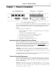
Chapter 1 - Network Installation 2 Chapter 1 - Network Installation Octal V.35-Quad 10/100 RIOP Front Panel This section of the manual will help you install the Octal V.35-Quad 10/100 RIOP to connect up to four local Ethernets and up to eight remote corporate networks. These connections can be made to other Compatible Systems devices or internetworking equipment from other vendors. In summary, the steps for installation are: 1.
Chapter 1 - Network Installation 3 The Octal V.35-Quad 10/100 RIOP is shipped with two “Quad” cables. These cables have a single Very High Density D-Sub connector which plugs into one of the Quad V.35 interface ports on the front of the device and then divides into four separate High Density D-Sub (HD D-Sub) female interface cables. v Note: Port numbers 0 - 3 are stamped on both sets of Quad cables. For ports 4 -7, the connector marked “Port 0” is Port 4, the connector marked “Port 1” is Port 5, etc.
Chapter 2 - Quickstart Instructions 4 Chapter 2 - Quickstart Instructions This Quickstart chapter briefly discusses the major parameters that must be set in order to use the Octal V.35-Quad 10/100 RIOP as part of your VSR multigigabit switching router. Detailed information on the meaning of the router’s parameters is provided in the CompatiView Management Software Reference Guide and the Text-Based Configuration and Command Line Management Reference Guide.
Chapter 2 - Quickstart Instructions 5 Suggested for IP These parameters help supply information about the segment that the interface is connected to. With this information, routing can take place. • Set IP RIP 1, IP RIP 2 or OSPF (Open Shortest Path First) • IP static routes CV: Use the TCP/IP Routing: Ethernet Dialog Box to set RIP, and the IP Static Routing Dialog Box (under Global/IP Static Routes) to set static routes. OSPF can only be configured using text-based configuration.
Chapter 2 - Quickstart Instructions 6 DECnet Protocol Required for DECnet The router’s shipping configuration does not have DECnet turned on. In order to be used, DECnet must be turned on both globally and for a particular port. • Set DECnet on (globally, and for this port) • Set DECnet area • Set DECnet node CV: Use the DECnet Routing Dialog Box (under Global/DECnet Routing) and the DECnet: Ethernet Dialog Box.
Chapter 2 - Quickstart Instructions 7 IP Protocol Required for IP WAN interfaces which are set for PPP operation do not generally use an IP address. They are set to act as an “unnumbered interface.” In this mode of operation, there are no required settings. Suggested for IP These parameters help supply information about the segment that the interface is connected to. With this information, routing can take place.
Chapter 2 - Quickstart Instructions 8 In CompatiView you must set a global parameter and a port-specific parameter. Suggested for DECnet Setting the parameters above should be adequate for most installations. Frame Relay Configuration This section covers the settings required for Frame Relay operation of the V.35 WAN interfaces. In general, the parameters listed here should be set for each WAN interface on which you plan to use Frame Relay.
Chapter 2 - Quickstart Instructions 9 IP Protocol There are two ways to set up Frame Relay. One is to set the WAN interface as a “numbered interface.” This means that the interface (and thus the Frame Relay network) will have an IP address, subnet mask, etc. The other is to set it as an unnumbered interface and specify that the link is point-to-point Frame Relay and set the local DLCI. Unnumbered Frame Relay can only be configured using text-based configuration. Instructions are provided for both options.
Chapter 2 - Quickstart Instructions 10 IPX Protocol Required for IPX Frame Relay operation requires that the WAN interface be set as a “numbered interface.” This means that the interface (and thus the Frame Relay network) must have an IPX network number. • IPX numbered interface • IPX network number CV: Use the IPX Routing: WAN Dialog Box. TB: Use configure and set the Numbered and Net keywords in the IPX WAN 0 (and/or any other port numbers you wish to configure) section.
Chapter 2 - Quickstart Instructions 11 SMDS Configuration This section covers the settings required for SMDS (Switched Multi-megabit Data Service) operation of the V.35 WAN interfaces (IP only). SMDS is a connectionless, packet-switched service that offers LAN-to-LAN connectivity across a wide area at up to 1.544 Mbps. SMDS addresses and other parameters can only be set using the command line interface.
Chapter 3 - Shipping Defaults Chapter 3 - Shipping Defaults Ethernet Interfaces IP Routing Defaults • Off, all interfaces IP Bridging Defaults • On, all interfaces • Address: 198.41.12.1 • Subnet Mask: 255.255.255.0 • Broadcast Address: 198.41.12.255 • IP RIP off IPX Routing Defaults • 802.3 on, autoseeding, all interfaces • 802.2 on, autoseeding, all interfaces • Type II on, nonseeding • 802.
Chapter 4 - LED Patterns 13 Chapter 4 - LED Patterns Some of the LEDs on the front of the VSR multigigabit switching router serve dual functions. In addition to indicating certain router-wide operating conditions, they may also display port-specific information. v Note: Any continuous flashing pattern not noted in this chapter may be caused by a hardware failure. Please call Compatible Systems Technical Support if your router shows a hardware failure.
Appendix A - Connector and Cable Pin Outs 14 Appendix A - Connector and Cable Pin Outs Pin Outs for HD D-Sub Male to V.35 Male Cable V.35 A B C D E F H P R S T U V W X Y AA 1 DTE – ↔ ↔ → ← ← ← → → ← → ← → ← → ← ← ← DCE Signal Chassis Ground Signal Ground Request to Send 1 Clear to Send 1 Data Set Ready 1 Receive Line Signal Detect 2 Data Terminal Ready 3 Tx Data + Rx Data + Tx Data – Rx Data – Tx Clock Out + 4 Rx Clock In + Tx Clock Out – 4 Rx Clock In – Tx Clock In + Tx Clock In – Unused by the V.