CVG-606xl 6x6 Video/Audio Matrix Switcher CVG-808xl 8x8 Video/Audio Matrix Switcher USER MANUAL
CONTENTS 1 INTRODUCTION 3 1.1 A Word on Video/Audio Switchers 3 1.2 Factors Affecting Quality of Results 3 2 SPECIFICATIONS 4 3 HOW DO I GET STARTED? 4 4 UNPACKING AND CONTENTS 5 4.1 5 Optional Accessories 5 GETTING TO KNOW YOUR MATRIX SWITCHER 5 5.1 Your CVG-606xl Matrix Switcher 5 5.2 Features of the CVG-606xl Matrix Switcher 5 6 INSTALLATION 8 Rack Mounting 8 6.1 7 CONNECTING TO VIDEO DEVICES 8 8 CONNECTING TO AUDIO DEVICES 8 9 USING THE MACHINES 8 9.
12 TROUBLESHOOTING 14 12.1 Power and Indicators 14 12.2 Video Signal 14 12.3 Audio Signal 15 12.4 Control 15 12.
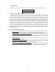
1 INTRODUCTION Congratulations on purchasing your Matrix Switcher. This user manual describes the following products: CVG-606xl CVG-808xl 1.1 A Word on Video/Audio Switchers A video/audio switcher usually switches between several sources (inputs) and one or more acceptors (outputs). A switcher that allows several inputs to be connected to several outputs simultaneously is called a Matrix Switcher. Switchers may be of the electronic or mechanical type.
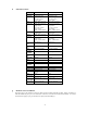
2 SPECIFICATIONS CVG-606XL CVG-808XL Configuration 6x6 6 composite video, Input Type 1 sync/video genlock with sync select switch, 6 stereo audio Video: BNC connectors Input Audio: RCA connectors Connections Composite video: Input Level 1Vpp/75ohm, Sync/video genlock: 1Vpp/75ohm Audio: +4dBm/62kohm Output Type 6 composite video 6 audio stereo Video: BNC connectors, Output Audio: RCA connectors Connector Output Level Composite video: 1Vpp/75ohm Audio: +4dBm/50ohm (27Vpp max.
4 UNPACKING AND CONTENTS The items contained in your CVG accessory package are listed below. Please save the original box and packaging materials for possible future transportation and shipment of the machine. Matrix Switcher CD with Control software AC Power Cable User Manual Null Modem Adapter Connector 4 Rubber Feet 4.1 Optional Accessories The following accessories, which are available from CVG, can enhance implementation of your machine.
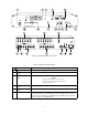
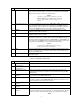
Figure 1: CVG-606xl Front/Rear Panel Features Table 1: CVG-606xl Front Panel Features No. 1. 2. 3. Feature Function Power Switch Illuminated switch: supplies power to the unit. OUTPUT SELECTOR Select the desired output that the input signal is switched to. buttons Select the desired input to be switched to the output. INPUT SELECTOR buttons NOTE Pressing input buttons "1", "2" and "3" together resets the machine and performs a 7-segment display test. 4. 5. 6.
No. Feature Function 7. STO illuminated button Should be pressed, followed by an input or output pushbutton to store the current status in the non-volatile memory. For example. Press STO followed by INPUT 4 button to store Setup # 4 in the non-volatile memory. NOTE To delete a setup from the memory, press the STO and RCL buttons simultaneously, followed by the input button (Setup number) to be deleted. 8. AFV illuminated button 9. AUDIO 10. VIDEO 11.
No. Feature Function Operation of the machine from a remote PC may be done using the control software (provided with the machine). 9. Setup DIP switches 10. Power Connector 6 INSTALLATION 6.1 Rack Mounting Allow proper configuration of the control signals received and transmitted through the RS-232 (or RS-485) control port, master/slave modifications, line termination and device ID numbers. A 3-prong AC connector allows power to be supplied to the unit.
9.2.2 Selecting an Input Input selection on the Matrix Switchers is made by pressing any of the buttons marked “1” through “8” (CVG808XL), or "1" to "6" (CVG-606XL) on the front panel. These buttons correspond to input connections as marked on the back panel. 9.2.3 Connecting a Video/Audio Input/Output To connect a video/audio Input to a specific output, press the desired output button (upper line), followed by the desired input button (lower row). 9.2.
9.3.1 Selecting the Sync Source Input sync selection is made using the "Sync Select” button located on the back panel. For an external sync operation, press the “Sync Select” button. For an internal sync operation, release the “Sync Select” button. This modifies the input circuitry to select the required input sync source. 9.3.2 Setting the Configuration Switches Setting the configuration switches is accomplished through a bank of DIP switches located on the back panel of each Matrix Switcher.
communication between Matrix Switchers is always via RS-485 (see example in Figure 5). The RS-232 port is either a DB-9 (9-pin port) or DB-25 (25-pin port). The cable connecting your switcher to the PC should be wired as shown in Figure 4. A 9-25 pin adapter or 9-9 pin null-modem adapter is included for your convenience. The null-modem adaptor is wired as shown in Figure 4.
10 TYPICAL APPLICATIONS 10.1 Basic Video-Audio Setup One of the most common video formats is composite video. Figure 7 describes a typical composite video setup using the CVG-808XL in this case. Three video-audio sources, three video-audio acceptors, and a genlock source are connected to the machine, while control of the Matrix Switcher is implemented via the PC using RS232 communication. Perform the following steps (as necessary): 1. 2. 3. 4.
The examples below detail the building of RGB matrices. The same principles may be used for YC (2 switchers), YUV (3 switchers), RGBS (4 switchers), and RGBHV (5 switchers). 10.2.1 RGB/YUV Switching with RS-232 (e.g. PC Control) For RS-232 control of the component matrix switcher, an additional piece of equipment would be required. Since RS-232 can only be used for control between 2 pieces of equipment (e.g. a PC and a switcher), we need a method of “distributing” the RS-232 to all 3 machines.
12 TROUBLESHOOTING 1. 2. NOTES Please note that if the output signal is disturbed or interrupted by very strong external electromagnetic interference, it should return and stabilize when such interference ends. If not, turn the power switch off and on again to reset the machine. If the recommended actions still do not result in satisfactory operation, please consult your CVG Dealer. 12.1 Power and Indicators Problem Remedy No power 1. 2. 3.
Problem Remedy Noise bars are "rolling" up or down in the output image or: Low Frequency Hum in the audio output Hum bars (ground loop) are caused by a difference in the ground potential of any two or more devices connected to your signal path. This difference is compensated by passing that voltage difference through any available interconnection, including your video cables.
12.5 Switching Malfunctions Problem Remedy The switcher succeeds in switching a number of sources then fails to switch one. Malfunction in the particular source or cable assembly. NOTE The most common failure mode in transferring the signal of an audio source is a break in the connecting wire. Disconnect the source from a channel that is switching successfully and connect the suspect source to it.
number which was switched. For disconnect, set as 0. For other operations, these bits are defined according to the table. 3rd BYTE: Bit 7 - Defined as "1". Bits 4-6 Defined as "0". O3 – O0 – “OUTPUT”. When switching via RS-232 or RS-485 (for instruction codes 1 and 2), the output to switch is set by these bits. Similarly, if switching is done via the machine’s keyboard, then these bits are set with the output number which was switched. For other operations, these bits are defined according to the table.
NOTES ON THE ABOVE TABLE: NOTE 1 - When the master switcher is reset, (e.g. when it is turned on), the reset code is sent to the PC. If this code is sent to the switchers, it will reset according to the present power down settings. NOTE 2 - These are bi-directional definitions. That is, if the switcher receives the code, it performs the instruction, and if the instruction is performed (due to a keystroke on the front panel), then these codes are sent.
TABLE OF HEX CODES FOR THE MASTER CVG-808xl The table below shows the “HEX” codes for switching the master CVG-808xl. The table is also valid for the CVG-606xl if the last two rows and columns are ignored.