
User guide

NT® INTEGRATED FLOW CONTROLLER WITH DEVICENET™ COMMUNICATION USER GUIDE
2 Customer Service Tel. 763-502-0200 Customer Service Fax 763-502-0300 ENTEGRIS, INC.
Introduction
This manual is for use with standard
NT
®
Integrated Flow Controllers
with DeviceNet
TM
communication,
Model 6500. These instruments have
been designed for use in high-purity
applications in the semiconductor
industry. The wetted parts are con-
structed with PTFE, PFA or other
similar high-purity inert materials.
WARNING!
Attempting to install or operate
standard NT® Integrated Flow
Controllers without reviewing the
instructions contained in this
manual could result in personal
injury or equipment damage.
Identifying Nonstandard
Product Configurations
This User Guide applies to product
manufactured as the standard NT
®
Integrated Flow Controller. Entegris
also manufactures nonstandard
product to meet the needs of specific
applications. Nonstandard product
may have different materials of con-
struction, accuracy specifications,
performance and other specifica-
tions that differentiate the non-
standard product from the standard
offering.
NOTE: Nonstandard NT® Integrated
Flow Controllers may be identified
by the model number found on the
product label. Specifications for
nonstandard NT® Integrated Flow
Controllers are available by contact-
ing Entegris.
Nonstandard NT
®
Integrated Flow
Controllers, Model 6500 product line,
are identified with an “M” followed
by a number code.
Example part number:
6500-T2-F02-AM6-D-P1-U1-M02
The “M02” designates the product
as a nonstandard product manu-
factured to certain specifications
designated under the “M02” code.
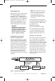
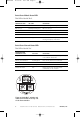
Principle of Operation
The user provides a set point signal
that corresponds to the desired
amount of flow. The standard NT
®
Integrated Flow Controller compares
the set point to the actual flow signal
from the flow module. If the actual
flow is greater than the set point, the
unit closes the valve. If the actual
flow is less than the set point, the
unit opens the valve. The flow con-
troller does this in a precise manner
until the actual flow signal is equal
to the set point.
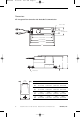
Figure 1: System block diagram
ENT48906 10/15/04 8:12 AM Page 2