INITIAL SET UP A. UNPACKING Remove all plastic film, cardboard and tape from the outside of the vendor. Loosen any shipping devices used to secure interior parts during shipment (backspacer, shims or spacers). To remove shipping boards from base, raise vendor on a well stabilized lifting device. Remove the leveling bolt which hold the boards in place and remove the boards. Replace bolts to equal heights in the threaded holes. Another method to remove shipping boards is to split the boards apart.
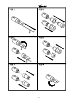
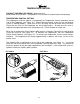
FIGURE 1 LOCK CODING The safest method to code the lock is to remove it and secure it in a vise or similar tool. The lock can also be recoded in the handle. (For the following steps refer to Figure 2) STEP 1 Insert key into lock. Insert pin into hole in cap. STEP 2: To release cap, push pin in firmly and rotate key to right slot position. Remove cap and key as one unit. STEP 3: Using magnet end of loading tool, remove all seven tumblers. STEP 4: Slip preloaded coder on lock. Place loading tool into coder.
S-3
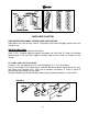
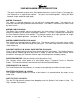
FIGURE 3 FIGURE 4 LABEL INSTALLATION COIN INSTRUCTION LABEL & PRICE LABEL APPLICATION: Apply labels to a clean and dry surface. Peel backing from label and apply to plate with a firm even pressure. INSTRUCTION LABEL (Refer to figure 3 for the following information.) Plate “A” has Validator Opening separate and above the Coin Plate “B” shows the Validator Opening built in the Coin Plate. Apply Instruction Label to area shown (as needed by the vendor).
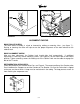
FIGURE 7 FIGURE 9 ALIGNMENT CHECKS DOOR ROLLER CHECK: The Door Roller assembly is raised or lowered by adding or removing shims, (see figure 7 ). Raising or lowering the roller will help ensure the proper alignment of the door lockstud to the cabinet latch. DOOR ALIGNMENT CHECK: After any door adjustment, the Quicker Lock should align itself automatically. If additional adjustment is necessary, loosen mounting screws, (see Figure 8), raise or lower latch to the correct position.
TEMPERATURE CONTROL PRODUCT TEMPERATURE CHECK: (Reference only) Allow vendor to run 24 hours. Vend product, insert test device (thermometer) into beverage. TEMPERATURE CONTROL SETTING: The temperature inside the cabinet is regulated by the Temperature Control, located on the left side of the Evaporator (see Figure 10 ). Before adjusting control, make sure the refrigeration system is working properly. Check that all fans run freely and do not make excessive noise.
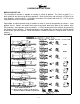
LOADING INSTRUCTIONS BASIC LOAD SET-UP: The Univendor-2 machine is capable of vending a variety of product. The Chart on page 7 is a basic guide for the load set-up of these products. Refer to the chart and the items in Figure 12 for each product’s setting and kits. Installation Instruction are included with each kit. Call a service representative for kits or further information. Open upper and lower product cage assemblies at front of stack to load product in columns. Load product evenly.
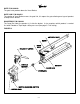
VEND MECHANISM PARTS DESCRIPTION The parts listed below are part of the Vend Motor Mechanism (refer to Figure 17 on page A6). One Mechanism is required per column. The parts are interchangeable. Setting will differ between single, double or triple depth. MOTOR: P/N 388637 This motor is a thermal protected, 115 volt, 60 hertz, shaded pole motor. The motor has an externally mounted spring loaded mechanical brake. The Motor is attached to the Mech. Plate by three screws.
GATE: P/N 1066082 The gate holds product above the Vend Bucket. GATE LINK: P/N 1008501 The rotation of Vend Bucket moves the gate link, this opens the gate allowing one layer of product to drop into the bucket. GAUGE BAR: P/N 1064333 The Gage Bar Holds the product (s) inside the bucket. It also regulates which product is vended first when Double or Triple depth setting are used (See page S-7 for setting).
VEND CYCLE Several operations take place during the Vend Cycle: a purchase is made, the cam and bucket rotate, product is dispensed and reloaded. The sequence of these operations change slightly when the column’s depth setting is changed. With the Single Depth Setting, one purchase is made and the bucket is reloaded, the Cam Sequence occurs once per bucket revolution. With the Double Depth setting, two purchases are made before the Bucket is reloaded, the Cam Sequence occurs twice per bucket revolution.
RELOADING SEQUENCE: (See Figure 15) RS 1. The gate link rests at a locked position, in a cutout on the mech. plate. This locked position prevents the gate from opening out of sequence. RS 2. The gate link is guided by a slot in the mech. plate and actuates by a ridge on the bucket. As the bucket turns, the link is moved out of the locked position. RS 3. As the link rises, the gate is opened. The spring maintains Pressure on the Link and the gate. RS 4. Product falls onto outside of the bucket. RS 5.
LIGHTING WIRING DIAGRAMS REFRIGERATION WIRING DIAGRAM S-12
REFRIGERATION OPERATION The refrigeration operation section is divided into three areas: Basic Refrigeration Principle. Detailed Vending machine Refrigeration cycle, and Parts Description. BASIC REFRIGERATION PRINCIPLE What a refrigeration system really accomplishes is the transfer of heat. A refrigeration system removes the excess heat from a refrigerated area and then transfers it to a condenser where it is dissipated. As heat is removed, the refrigerated area cools.
DETAILED REFRIGERATION CYCLE The following is a detailed refrigeration cycle as it applies to the refrigeration system installed in Vendo equipment. (Refer to the flow chart in Figure 16) As the temperature in the cabinet rises, the liquid in the thermostat feeler bulb also rises in temperature. As this liquid becomes warmer, it expands. This expanding liquid expands against the temperature control bellow which operates the temperature control switch.
FIGURE 16 REFRIGERATION PARTS DESCRIPTION The Compressor, Condenser, Drier, Capillary Tube, Evaporator, and Accumulator are part of a sealed system (refer to figure 16). These items are not available separately. For the part number of the sealed refrigeration system refer to the common parts section of the manual. COMPRESSOR The compressor takes in low pressure vapor and compresses it, increasing both the pressure and the temperature. The hot high pressure gas is forced out to the condenser.
REFRIGERATION PARTS DESCRIPTION (CONTINUED) CAPILLARY TUBE The capillary tube controls, at a steady rate, the flow of refrigerant liquid to the evaporator. It has a very small inside diameter to keep pressure in the evaporator low while the pressure in the condenser is high. It is the connecting link between the condenser and evaporator. EVAPORATOR The Evaporator is a heat transference device. It removes the heat from the air in a refrigerated space and transfers it to the refrigerant liquid.
(The parts listed below are not part of the sealed refrigeration system and are available separately. For part numbers, see the refrigeration assembly in the common parts section of the manual.) CONDENSER FAN ASSEMBLY The condenser fan pulls cool air from outside the vendor, through the condenser, over the compressor and blows it out the back of the vendor. This cool air removes excess heat from refrigerant in the condenser. The condenser fan runs when the compressor is engaged.
MAINTENANCE The following section is a basic guide for general maintenance and servicing of the Vendor . This section is divided into four parts: (I) Preventative Maintenance, (II) Lubrication Guide, (III) Care and Cleaning, (IV) Basic Trouble Shooting. I. PREVENTATIVE MAINTENANCE SUGGESTIONS: When ever a Vendor is visited on its site, the following service should be performed. Preventative maintenance will help prevent future problems with the Vendor. A. B. C. D. E. F. G. H. I. J. K. L. M. II.
III. CARE AND CLEANING A. GENERAL PROCEDURE ( painted metal areas) Wash Vendor with soap and water. The exterior may be waxed with any good automobile wax. B. FRESH PAINT SPLASHES, GREASE, GLAZING COMPOUND REMOVAL Before drying, these elements may be removed by rubbing lightly with grade “A” Naptha (or equivalent grade solvent). After removal, use general cleaning procedure (listed above as A) C. LABELS AND STICKER REMOVAL Use Kerosene, VM&P grade Naptha or petroleum spirits for removal.
TROUBLE-SHOOTING GUIDE This guide is a general list of probable problems, causes, and solutions. For problems not listed or additional question, contact the Field Service Department at Vendo, 7209 N. Ingram Ave., Fresno, CA 93650 or call 1-800-344-7216. Please have the maufacturer’s date code and model number of the vendor when you call. The trouble-shooting guide is divided into three columns: First Column, Possible Problem; Second Column, Possible Cause; Third Column, Service Suggestion.
POSSIBLE PROBLEM Money accepted no product vended POSSIBLE CAUSE No selections work No. 1 selection works, No. 2 thru last does not. Soldout Switch (of column selected) inoperative Motor starts, does not run Vend motor runs until two or three products are vended or vend motors run continuously. Refrigeration unit will not run at all Compressor will not start SERVICE SUGGESTION Check No.1 selection switch, replace if necessary. Check No 2. section switch, replace it necessary.
condenser fan motor running - inoperative unit hot (power to compressor) Compressor inoperative Compressor starts but does not run Will not cycle Starting relay stays closed Thermostat inoperative Compressor runs but cabinet temperature warm Compressor motor problem Loss of refrigerant Condenser fan not working Blocked or dirty condenser (refer to initial installation in the service manual) Evaporator fan not working Bad inner door seal S-22 replace Disconnect power to vendor, remove all leads from
POSSIBLE PROBLEM Compressor runs, but cabinet temperature warm Compressor runs continuously Evaporator frosted over Product freezing up too cold Excessive noise POSSIBLE CAUSE Thermostat set too high SERVICE SUGGESTION Adjust thermostat (see initial set up of service manual) Thermostat inoperative Check thermostat Water at base of evaporator Check for proper drainage unit (such as plugged drain, kinks in drain tube, etc.
A COMMITMENT TO SAFETY The Vendo Company is committed to safety in every aspect of our product design. Vendo is committed to alerting every user to the possible dangers involved in improper handling or maintenance of our equipment. The servicing of any electrical or mechanical device involves potential hazards, both to those servicing the equipment and to users of the equipment. These hazards can arise because of improper maintenance techniques.
SECTION I: VENDOR INSTALLATION A. Vendors are large, bulky machines of significant size and weight. Improper handling can result in injury. When moving a vendor, carefully plan the route to be taken and the people and equipment required to accomplish the task safely. B. Remove all tape, shipping sealant, and Styrofoam from the vendor. Loosen any shipping devices used to secure interior parts during shipping. Remove the wooden shipping base, attached to the vendor base by the vendor leveling screws.
Page 3
SECTION I: VENDOR INSTALLATION (CONT’D) For Type 1 and Type 2 outlets, test for Grounding and Polarization as follows: 1. With a test device (volt meter or test light), connect one probe to the receptacle’s Neutral contact and the other to the Live contact. The test device should show a reaction. 2. Connect one probe to the receptacle’s Earth contact and the other to the Live contact. The test device should show a reaction. For Type 3 through Type 5 outlets, test for Grounding as follows: 1. 2.
SECTION I: VENDOR INSTALLATION (CONT’D) G. Door Support (Fig. 2) The door support may be raised or lowered by adding or removing shims, to insure that the outer door closes squarely to the cabinet. Raising or lowering the door support can also insure proper alignment of the door latch. FIGURE 2 H. Door Latch Alignment (Fig. 3) After any door adjustment, the floating Quicker Lock assembly should align itself automatically. The latch assembly is adjustable.
SECTION II: ELECTRICAL HAZARDS GENERAL Vendo vending machines are provided with the appropriate power supply setting for your area. Some models are equipped with step-down transformers, as required, enabling the vending machines to operate on different mains voltages. Refer to section I. E. for information to determine the main power requirements. Refer to the appropriate Service Manual for details of step-down transformer operation.
SECTION II: ELECTRICAL HAZARDS (CONT’D) B. Servicing with “Power Off” For maximum safety, unplug the service cord from the wall outlet before opening the vendor door. This will remove power from the equipment and avoid electrical and mechanical hazards. Service personnel should remain aware of possible hazards from hot components even though electrical power is off. See the appropriate sections of this manual for further information. C.
SECTION III: MECHANICAL HAZARDS A. Servicing of Moving Parts and Assemblies When servicing assemblies involving moving parts, use extreme caution!! Keep fingers, hands, loose clothing, hair, tools, or any foreign material clear of entrapment. As noted before under the Electrical Hazards section, “Power On” servicing should only be performed by qualified personnel. Refer to and heed the warnings noted in Electrical Hazards section.
SECTION IV: REFRIGERATION HAZARDS GENERAL Refrigeration systems involve both electrical power and mechanical action. These systems may present any of the potential dangers shown in the sections on Electrical and Mechanical Hazards contained in this manual. See Sections II and III for further information. A. Compressed Refrigerant Refrigeration systems involve the compression and evaporation of gases. The pressures contained represent a potential hazard if suddenly released in confined areas.
SECTION VI: SUBSTITUTIONS AND MODIFICATIONS GENERAL Unauthorized changes or the substitution of unauthorized parts can compromise the equipment designs. This can result in unsafe conditions for either the service personnel or the equipment users. Always refer to the appropriate Parts and Service Manual for replacement parts and maintenance instructions. If questions arise, contact the Technical Services Department of the Vendo office in your area. (Consult the listing at the end of this manual.
SECTION VI: SUBSTITUTIONS AND MODIFICATIONS (CONT’D) B. Service Cord Replacement (For 240 Volt System Used in the United Kingdom) As the color of the wires in the mains lead of the vending machine may not correspond with the colored markings identifying the terminals in your plug, proceed as follows: The wire which is colored Green and Yellow must be connected to the terminal in the plug which is marked with the letter E or by the earth symbol or colored Green or Green and Yellow.
SECTION VII: CONSUMER SAFETY WARNING WARNING: VENDOR CAN BE OVERTURNED IF SUFFICIENT FORCE IS APPLIED, AND MAY RESULT IN SERIOUS INJURY OR DEATH. GENERAL There have been incidents, including fatalities, when vending machines have been vandalized by being pulled over in an attempt to obtain free product or money. To warn of the danger involved in tipping, shaking, or rocking the vending machine, a decal has been designed to be affixed to vending machines.
PARTS, SALES, & SERVICE CENTERS OF VENDO/SANDEN COMPANY AREA ADDRESS PHONE NUMBERS United States, Canada The Vendo Company Tel: (209) 439-1770 7209 N. Ingram Fax: (209) 439-2083 Fresno, CA 93650 U.S.A. Japan Sanden International Corporation Tel: (03) 3835-1321 31-7 Taito 1-Chome Fax: (03) 3835-3169 Taito-ku Tokyo 110, Japan Europe, Mid-East, Vendo GMBH Tel: (211) 746012 Africa, U.S.S.R. Spangerstr. 22 Fax: (211) 7488541 D-40599 Dusseldorf Germany Australia, Sanden International Pty. Ltd.
PARTS, SALES, & SERVICE CENTERS OF VENDO/SANDEN COMPANY FOR LATIN AMERICA AREA Mexico Central America Chile Brazil South America ADDRESS Vendo de Mexico Camino Real de Toluca No. 154 Col. Bellavista 01140 Mexico D.F. Mexico Midland Inter-American, Inc. 700 West 48th Street Kansas City, MO 64112 U.S.A. Sidex San Juan 4519 - San Joaquin Santiago de Chile Cimaq Industria e Comercio de Maq, Ltda. Estrada Uniao e Industria, 9.120 Itaipava 25730-730 Petropolis Rio de Janeiro, Brazil The Vendo Company 7209 N.
READING A PARTS LIST I ITEM NUMBER is found in two locations: A. It is on the drawing plate, and identifies the part and its location; B. The same number is in the parts lists and ties the two together. II PART NUMBER is the part number that has been assigned to a specific part by Vendo, for easier identification. III QUANTITY REQUIRED relates to the amount required of a part, or will be indicated by “A/R” as required to attach it to another part.
DESCRIPTION INNER - OUTER DOOR LOCK T-HANDLE LOCK COVER KIT - TRADE T-HANDLE LOCK COVER KIT - COCA COLA T-HANDLE LOCK COVER KIT - DR PEPPER T-HANDLE LOCK COVER KIT - PC 95’ CROWN BOX KIT - COKE VENDOR SUPPORT KIT - BLACK BRACKETS BILL VALIDATOR ADAPTER KIT INNER DOOR GASKET - 72” INNER DOOR GASKET - 79” CASTER KIT CASTER W/ BRAKE KIT COIN BOX LOCK KIT NUMBER 1087511 1047795 1047779 1051503-1 1051503-4 133555-1 133666 133585 389622-3 389622-4 133513 133513-1 1087759 6.02 1.
1 25 24 2 35 36 37 31 34 32 33 29 3 28 30 4 5 23 22 6 21 7 13 38 14 9 8 19 15 10 11 20 18 17 12 26 16 39 27 40 A-3
“UNIVENDOR - 2” CABINET ASSEMBLY ITEM NO.
1.
“UNIVENDOR - 2” STACK ASSEMBLY ITEM NO. 1* 2 3 4 5 6 7 8 9 10 11 12 13 14 15 16 17 18 ~ ~ 19 20 21 ~ 22 23 24 25 26 27 28 29 30 31 32 33 34 35 36 37 38 39 40 41 42 43 44 MODEL NUMBER REQ.
1.
“UNIVENDOR - 2” REFRIGERATION ASSEMBLY ITEM NO. 1 2 3 4 5 6 7 8 9 10 11 12 13 14 DESCRIPTION REQ. PART NO.
UNIVENDOR - 2 PARTS & SERVICE 1039261-E Trade Parts Section 6.
E1
“UNIVENDOR-2” TRADE OUTER DOOR (CURVED) ITEM NO. *1 2 3 4 5 6 7 8 9 10 11 12 13 14 15 16 17 18 19 20 21 MODEL NUMBER DESCRIPTION REQ. OUTER DOOR ASSEMBLY 1 SIGN CAP - TOP 1 SIGN FACE 1 BUSHING HINGE 2 FLAT WASHER - BOTTOM 2 SIGN TRIM - LEFT 1 SIGN CAP - BOTTOM 1 EYELET TRIM 1 CROWN PULLER PLUG 1 COIN RETURN CUP WELD 1 DRAIN TUBE 1 WATER COLLECTION TRAY 1 LABEL - RECYCLE 1 DBV WINDOW PLATE 1 LABEL - INSTRUCTIONS 1 DBV PLATE MOUNT 1 RETAINER - DISPLAY 1 DOOR GUARD 1 RAIN GUARD 1 COIN INSERT (REFER TO PG.
1.
“UNIVENDOR-2” TRADE OUTER DOOR CURVED (CONTINUED) ITEM NO. 23 24 25 26 27 28 29 30 31 MODEL NUMBER DESCRIPTION REQ. DOOR WELD ASSEMBLY 1 STRAP REMOVEABLE 1 DELIVERY HOPPER ASSEMBLY 1 COIN BOX 1 COINAGE DOOR ASSEMBLY 1 COIN RETURN CHUTE 1 INNER DOOR HINGE - MALE 2 RAIN GUTTER 1 CURVED LIGHT ASSEMBLY(REFER TO PG. E19 - E20) 1 511 PART NO. ~ 1075503 133574-10 134307 1056198 1002333 1121287 388581-1 ~ 601 PART NO.
1.
“UNIVENDOR-2” TRADE OUTER DOOR (FLAT) ITEM MODEL NUMBER 511 NO. DESCRIPTION REQ. PART NO.
1.
“UNIVENDOR-2” TRADE OUTER DOOR FLAT(CONTINUE) ITEM NO. MODEL NUMBER 511 DESCRIPTION REQ PART NO. . 24 DOOR WELD ASSEMBLY 1 134442-133 25 STRAP - REMOVEABLE 1 1075503 26 DELIVERY HOPPER ASSEMBLY 1 133574 27 COIN BOX 1 134307 28 COINAGE DOOR ASSEMBLY 1 1056198 29 COIN RETURN CHUTE 1 1002333 30 INNER DOOR HINGE - MALE 2 1121287 31 RAIN GUTTER 1 388581-1 32 FLAT LIGHT ASSEMBLY (REFER TO PG. E21-E22) 1 ~ *NOTE: WHEN ORDERING OUTER DOOR ASSEMBLY, PLEASE PROVIDE 9-CODE AND MANUFACTURER’S DATE CODE. 601 PART NO.
5 1 3 2 11 4 10 6 10 10 10 8 7 3 9 1.
“UNIVENDOR-2” TRADE OUTER DOOR (3/4 FLAT) ITEM NO. *1 2 3 4 5 6 7 8 9 10 11 DESCRIPTION OUTER DOOR ASSEMBLY SIGN FACE TRIM - SIDE SIGN FACE TRIM - TOP/BOTTOM SIGN FACE RETAINER DOOR FRAME DOOR GUARD, BLACK SIGN FACE RETAINER SIGN FACE LOWER PANEL SCREW CARRIAGE BOLT MODEL NUMBER REQ. 1 1 2 1 1 1 1 1 1 A/R A/R 511 PART NO. * 388284-6B 388284-3B 1079805 134442-133 2004058 1079821 ** 388453 V801489 V801434 *NOTE: WHEN ORDERING OUTER DOOR ASSEMBLY, PLEASE PROVIDE 9-CODE AND MANUFACTURER’S DATE CODE.
16 17 18 15 14 19 20 21 19 22 38 39 24 25 40 26 27 28 37 29 23 30 31 23 45 32 44 33 43 34 42 35 41 36 13 12 2 3 4 11 46 PUS H SOL D OUT PUS 10 9 8 H SOL OUTD PUS H SOL OUTD PUSH 7 SOL D OUT 6 PU SH PUS SO LD OU T H SOL D OUT PUS H SOL D OUT PUS H SOL D OUT 5 PUS H SOL D OUT PUS H SOL D OUT PUSH SOL D OUT 1.
“UNIVENDOR-2” TRADE SELECTION PANEL ITEM NO. 1 2 3 4 5 6 7 8 9 10 11 12 13 14 15 16 17 18 19 20 21 22 23 24 25 26 27 28 29 30 31 32 33 34 35 36 37 MODEL NUMBER DESCRIPTION REQ.
16 17 18 15 14 19 20 21 19 22 38 39 24 25 40 26 27 28 37 29 23 30 31 23 45 32 44 33 43 34 42 35 41 36 13 12 2 3 4 11 46 PUS H SOL D OUT PUS 10 9 8 H SOL OUTD PUS H SOL OUTD PUSH 7 SOL D OUT 6 PU SH PUS SO LD OU T H SOL D OUT PUS H SOL D OUT PUS H SOL D OUT 5 PUS H SOL D OUT PUS H SOL D OUT PUSH SOL D OUT 1.
“UNIVENDOR -2” TRADE SELECTION PANEL (CONTINUED) ITEM NO. 38 39 40 41 42 43 44 45 46 MODEL NUMBER DESCRIPTION REQ. COIN INSERT 1 COVER PLATE - COIN INSERT 1 DECAL - COIN INSERT 1 BUTTON COIN RETURN 1 GUIDE PLATE - COIN RETURN/INSERT 1 LENS- DISPLAY 1 PCB - DIGITAL DISPLAY 1 PLATE -DISPLAY COVER 1 BUTTON PANEL - 10 SELECT 1 511 PART NO. 1033026 1041355 1044907-1 1050473 1050481 1039652 1089678 1002597 2000252 601 PART NO. 1033026 1041355 1044907-1 1050473 1050481 1039652 1089678 1002597 2000252 1.
15 14 13 16 17 18 19 20 18 21 37 38 23 24 39 25 26 27 36 28 22 29 44 30 22 43 31 42 32 33 41 40 34 35 12 11 9 ELECTRONIC 7 10 4 5 1 2 6 3 1.
UNIVENDOR-2 TRADE SELECTION PANEL ITEM NO. 1 2 3 4 5 6 7 8 9 10 11 12 13 14 15 16 17 18 19 20 21 22 23 24 25 26 27 28 29 30 31 32 33 34 35 36 MODEL NUMBER DESCRIPTION REQ.
15 14 13 16 17 18 19 20 18 21 37 38 23 24 39 25 26 27 36 28 22 29 44 30 22 43 31 42 32 33 41 40 34 35 12 11 9 ELECTRONIC 7 10 4 5 1 2 6 3 1.
“UNIVENDOR-2” TRADE SELECTION PANEL (CONTINUED) ITEM NO. 37 38 39 40 41 42 43 44 MODEL NUMBER REQ. COIN INSERT 1 COVER PLATE - COIN INSERT 1 DECAL - COIN INSERT 1 BUTTON COIN RETURN 1 GUIDE PLATE - COIN RETURN/INSERT 1 LENS - DISPLAY 1 PCB - DIGITAL DISPLAY 1 PLATE - DISPLAY COVER 1 DESCRIPTION 601 PART NO. 1033026 1041355 1044907-1 1050473 1050481 1039652 1089678 1002597 1.
1.
“UNIVENDOR - 2” TRADE INNER DOOR ASSEMBLY ITEM NO. 1 2 3 4 5 6 7 8 9 DESCRIPTION INNER DOOR ASSEMBLY (FINAL) 10-16 x 1/2 HEX SCREW HINGE - FEMALE FLAP -DOOR (REVERSIBLE) PIN - HINGE GASKET - INNER DOOR KNOB - INNER DOOR GROMMET 1/4 - 20 CARRIAGE BOLT MODEL NUMBER REQ. 1 10 2 1 1 1 1 2 1 511 PART NO. 134302-33 V801489 1121286 1013076 389985 389622-3 388305 388090 V329258 601 PART NO. 134302-34 V801489 1121286 1013076 389985 389622-4 388305 388090 V329258 1.
1 2 10 3 15 5 12 14 17 4 16 8 2 11 13 6 10 7 9 8 8 1.
“UNIVENDOR -2” TRADE LIGHT ASSEMBLY (CURVED) ITEM NO. DESCRIPTION 1 LIGHT ASSEMBLY 2 BRACKET - LAMPHOLDER - CURVED 3 LAMP HOLDER - PLUNGER 4 LAMP HOLDER - FIXED 5 FLUORESCENT LAMP 6 BALLAST - LAMP 7 LIGHT HARNESS 8 HH SELF-DRILL SCREW #10 - 16 x ½ 9 RAMP/CATCH - INNER DOOR 10 SHEAR PANEL - UPPER/LOWER 11 HARNESS TIE 12 BUMPER - DOOR 13 GROMMET 14 SHEAR PANEL - MIDDLE 15 RAIN GUTTER 16 CLAMP - PUSH MOUNT 17 SCREW 10 - 16 x 5/16 MODEL NUMBER REQ. 1 4 2 2 2 1 1 AR 1 1 2 1 1 1 1 2 A/R 511 PART NO.
1 13 16 2 3 15 5 12 18 17 4 8 2 11 14 6 10 7 9 8 1.
“UNIVENDOR -2” TRADE LIGHT ASSEMBLY (FLAT) ITEM NO. DESCRIPTION 1 LIGHT ASSEMBLY 2 BRACKET - LAMPHOLDER - FLAT 3 LAMP HOLDER - PLUNGER 4 LAMP HOLDER - FIXED 5 FLUORESCENT LAMP 6 BALLAST - LAMP 7 LIGHT HARNESS 8 HH SELF-DRILL SCREW #10 - 16 x ½ 9 RAMP/CATCH - INNER DOOR 10 SHEAR PANEL - LOWER 11 HARNESS TIE 12 BUMPER - DOOR 13 SAIL PANEL 14 GROMMET 15 SHEAR PANEL - MIDDLE 16 RAIN GUTTER 17 CLAMP- PUSH MOUNT 18 SCREW 10-16 x 5/16 MODEL NUMBER REQ. 1 4 2 2 2 1 1 AR 1 1 2 1 2 1 1 1 2 A/R 511 PART NO.
1 23 3 2 22 4 21 20 5 19 13 4 18 12 17 11 16 15 14 10 2 4 7 8 9 4 E25 4 6 4
“UNIVENDOR -2” TRADE LIGHT ASSEMBLY (3/4 FLAT) ITEM NO. 1 2 3 4 5 6 7 8 9 10 11 12 13 14 15 16 17 18 19 20 21 22 23 MODEL NUMBER DESCRIPTION REQ.
2 11 3 6 10 4 9 5 8 1 6 13 7 16 12 15 14 17 1.
“UNIVENDOR - 2” TRADE ELECTRONIC CONTROL ITEM NO. 1 2 3 4 5 6 7 8 9 10 11 12 13 14 15 16 17 18 DESCRIPTION ELECTRONIC CONTROL ASSEMBLY PCB STANDOFF PCB ELECTRONIC CONTROL COVER - PCB ELECTRONIC CONTROL BRACKET - DOOR SWITCH RIVET DOOR SWITCH CLAMP - PUSH MOUNT MOUNTING BRACKET SCREW - 10-16 x 1/2 CR HEX SELF DRILL PLATE - COVER HOOK HARNESS - DOOR HARNESS - DOOR SWITCH HARNESS - POWER TRANSFORMER HARNESS - DISPLAY HARNESS - POWER HARNESS - SELECTION HARNESS - DEX/UCS (NOT SHOWN) REQ. PART NO.
THE VENDO COMPANY 7209 North Ingram Ave Fresno, CA 93650 Phone (800) 344-7216 - Fax (800) 541-5684 VEC 5.1-1061 - 1067 Programming Guide DOOR OPEN CONTROL SEQUENCE 1. 2. 3. 4. Diagnostic Error Codes Sales Information Alternate Test Vend Control Operation & Programming PROGRAMMING CHECKLIST NOTICE: Do not enter the programming modes of this control without authorization and proper training. The leading cause of vendor malfunction is a control board that is not properly programmed.
ERROR CODES ERROR CODE ACTION TO REMOVE ERROR CODE No action needed No Error Code to remove. Control board will automatically go to total historical vends. Press Mode Switch 1 time to identify jammed column(s) Remove cause of motor jam and test vend all columns vended by that motor.
STS Assignment Error (SSS) “ER-9” MDB Bill Validator Error (Valid only with MDB Interface) “SS_” = Unassigned Switch(es) “UA_” = Unassigned Column (5.1 Only) “DA_” = Doubly Assigned Column (5.1 Only) Press Mode Switch 1 time to identify: “BOPN” = Bill Box Open “BS” = Bill Validator Sensor Error “BJ” = Bill Jammed “BILL” = Defective Motor “BRCH” = ROM Checksum Error “BFUL” = Bill Box Full (5.1 Only) Automatically cleared when assignment error is corrected through SSS program mode.
ALTERNATE TEST VEND DISPLAY HOW TO DISPLAY Control board automatically reverts to this display from “Sales Information” Or “Control Operation & Programming” after 15 seconds (With inner and outer doors of inactivity. separated) “.00” OR “(VEND PRICE)” ACTION All vend and cash activities effect special test meters (counters) only and will not change normal (Door Closed) vend or cash meters.
CONTROL OPERATION & PROGRAMMING SUMMARY MODE OPTIONS “OPTS” (Press Mode Switch Four Times) OPERATION Bill Handling Press Selection Switch #1 (Continue to press #1 until desired setting is reached.) Correct Change Acceptance Press Selection Switch #2 (Continue to press #2 until desired setting is reached.) Zero Indicator Press selection switch #3 (Continue to press #3 until desired setting is reached.) Fast Price Set Press selection switch #4 (Continue to press #4 until desired setting is reached.
CONTROL OPERATION & PROGRAMMING SUMMARY MODE OPTIONS TWO “OPT 2” (Press Mode Switch Five Times) Options 2 Is Used Only On Models With VEC 5.1-1061. All Settings Should Remain At Factory Unless Special Applications Apply. OPERATION RESULT/RESPONSE Acceptance Non-Tube Coins (Special application Only) Press selection switch #1 (Continue to press #1 until desired setting is reached.
CONTROL OPERATION & PROGRAMMING SUMMARY MODE SPACE TO SALES “SSS” (Press Mode Switch Six Times) OPERATION RESULT/RESPONSE TO DISPLAY CURRENT COLUMN TO SELECTION CONNECTIONS: Press and release any selection Displays current column(s) connected to that selection TO CONNECT AND DISCONNECT COLUMNS FOR A SELECTION: Press and release the Display shows “CO 1” (Column 1). Displayed column number may or may selection to be changed. not flash.
CONTROL OPERATION & PROGRAMMING SUMMARY MODE PREPROGRAMED SPACE-TO SALES CONFIGURATIONS QUICK SET SSS SETTING 10 9 8 7 6 5 4 3 2 1 “SSSS” SEL # COL COL COL COL COL COL COL COL COL COL (Press Mode Switch Six 1 1 1,2 1 1,2 1 1 --- --- 1 1 Times to Display SSS. 2 2 3 2 3 2 2 --- --- --- 2 Then Press Reset Button Twice.
VENDO WARRANTY NEW EQUIPMENT I. This is Limited Warranty. II. The Vendo Company warrants, to the original purchaser, each part of each new vending machine for a period of fifteen (15) months from the date of shipment, to be free from defects in material and workmanship. This Warranty DOES NOT include light bulbs, fluorescent tubes, fuses, finish, or operating supplies.