
Service manual


VEND MECHANISM PARTS DESCRIPTION
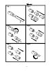
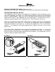
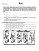
The parts listed below are part of the Vend Motor Mechanism (refer to Figure 17 on page A6).
One Mechanism is required per column. The parts are interchangeable. Setting will differ
between single, double or triple depth.
MOTOR: P/N 388637
This motor is a thermal protected, 115 volt, 60 hertz, shaded pole motor. The motor has an
externally mounted spring loaded mechanical brake. The Motor is attached to the Mech. Plate
by three screws.
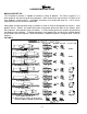
MOTOR CAM: P/N 390360
The Motor Cam assembly consists of two parts, the Cam and the Cam Retainer The Cam
controls the Motor Carrier and the Start/Bypass Switches. The Cam is Attached to the Motor by
the Cam Retainer (Retainer P/N 389401). The Retainer rotates left or right, provides for single,
double, or triple depth operation. (see page S-7 for Cam Settings)
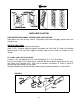
MOTOR CARRIER SWITCH: P/N 388687
Two switches are located below the Motor Cam. The outside switch is the motor carrier switch.
This switch holds the motor on though the vend cycle. The motor stops when the motor Carrier
switch drops out.
SOLDOUT SWITCH: P/N 368299 / BASE SWITCH: P/N 388303
There is one Soldout Switch and one Base Switch above the Vend motor. The Soldout Switch is
actuated by the Soldout flap when the column is empty. It stops the motor from running. When
all columns are empty the Electronic Control stops the coinage from accepting money.
SELECTION SWITCH: (See part Section of the Manual for P/Ns.)
The selection switch sends power to a Vend Motor when a Customer Presses a Selection
Button. The Selection Switches are beneath the Selection Button/Windows.
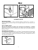
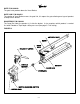
VEND BUCKET: P/N 1060139
The Vend Bucket holds the product(s) in a ready to vend position at the base of each column.
ADAPTER COUPLING: P/N 1027042
The Adapter coupling couples the motor to the bucket. It is located behind the motor, on the
motor shaft.
ANTI-TILT CLIP: P/N 389712
The Anti-Tilt Clip prevents product from dropping out of the Bucket if the Vendor is tilted. The
Clip is located in the bucket.
S-8