026-1702 Rev 0 10-30-00 Radio Frequency (RF) Temperature Sensor System Installation and Operation Manual
1640 Airport Road, Suite 104 Kennesaw, GA 31044 Phone: (770) 425-2724 Fax: (770) 425-9319 ALL RIGHTS RESERVED. The information contained in this manual has been carefully checked and is believed to be accurate. However, Computer Process Controls, Inc. assumes no responsibility for any inaccuracies that may be contained herein. In no event will Computer Process Controls, Inc.
Table of Contents 1 OVERVIEW ................................................................................................................................................................... 1 1.1. SYSTEM DESCRIPTION .................................................................................................................................................. 1 1.2. HARDWARE COMPONENTS .......................................................................................................................
5.3.1. Setting up the RF Gateway to Receive ID Transmissions ................................................................................... 18 5.3.2. Hand-Held Terminal Screen Navigation Tips..................................................................................................... 19 5.4. VERIFYING SUCCESSFUL COMMISSIONING ................................................................................................................. 19 5.5. DECOMMISSIONING A SENSOR FROM THE RF GATEWAY ....
1 Overview CPC’s Radio Frequency (RF) Sensor System provides refrigerated case temperature monitoring and control without the time and expense required to wire multiple temperature sensors from the cases back to the area controllers. All sensors in the RF Sensor System family are completely wireless, transmitting their values to receivers in the store area that pass them back to the area controllers.
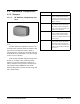
1.1. Hardware Components 1.1.1. Sensors 1.1.1.1.
1.1.1.2.
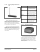
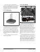
The sensing element and transmitting antenna for the RF Product Sensor are inside the enclosure and may transmit to receivers up to 150 feet away. The sensor also has an internal clean switch, which is activated by pressing a button on the enclosure. 1.1.3. RF Gateway 1.1.2. RF Receiver Figure 1-6 - RF Gateway Board Figure 1-5 - RF Receiver The RF Receiver (P/N 837-3510) is an antenna that mounts to the ceiling of the sales area or on top of a refrigerated case.
1.1.4. Hand-Held Terminal Figure 1-7 - Hand-Held Terminal (HHT) The Hand-Held Terminal (HHT) (P/N 8113110), shown in Figure 1-7, connects directly to the RJ11 jack on an RF Gateway and is used to commission RF Sensors and view the status of the system.
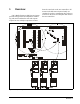
2 Installing the RF Gateway Installing the RF Gateway device for a site controller involves mounting and powering the device, connecting to the CPC controller’s RS485 network, and networking the RF Gateway with other gateways and receivers on-site. Figure 2-1 shows how to connect the 56VA and 100VA transformers to the RF Gateway power connector. Figure 2-2 shows how to connect the 175VA transformer to the RF Gateway.
2.3.1. Wire Connection Using shielded three-conductor network cable (Belden #8641 or equivalent), connect the RS485 I/O Network wire to the three-terminal connector on the RF Gateway board as shown in Figure 2-3. For further information about how RS485 networks are configured, refer to your site controller’s user manual. Figure 2-3 - Connecting the RF Gateway to the RS485 Network Figure 2-2 - Pinout for the 175VA (640-0048) Transformer 2.3.
Figure 2-5 - Dip Switch Setting for Numbering RF Gateway 2.3.4. Setting the RS485 I/O Termination Jumpers Figure 2-4 - Dip Switch Setting for Numbering RF Gateway 2.3.3. Setting the Baud Rate Dip Switch Dip switches 6 and 7 control the baud rate at which the RF Gateway communicates with the site controller on the RS485 Network. These switches must be set to the same baud rate setting as the Einstein or REFLECS (usually 9600 baud).
2.4. Networking Gateways and Receivers (Token Ring Network) The RS485 Token Ring Network interconnects all RF Gateways and Receivers on the site. Like the RS485 I/O Networks that interconnect the area controllers, input boards, output boards, and RF Gateways, the Token Ring Network must be set up in a daisy chain configuration. All devices must be wired together in a single chain as shown in Figure 2-7, with no branches and with no device connected to more than two other devices.
3 Installing the RF Receiver Installing an RF Receiver requires mounting the receiver, powering the receiver, and networking the receiver together with other receivers and gateways on the RS485 Token Ring Network. 3.1. Mounting and Placement of the RF Receiver 3.1.1. Environmental Operating Conditions The RF Receiver should be mounted in an environment with ambient temperature between 30°F and 120°F, with a non-condensing relative humidity between 5% and 95%. 3.1.2.
3.3.1. Wire Connection Connect the Token Ring Network wire to the three-terminal connector on the RF Receiver board as shown in Figure 3-1. work Termination Jumpers The devices at each end of the Token Ring Network daisy chain must be terminated. To terminate the Token Ring Network at the RF Receiver, set the jumpers to the UP position, as shown in Figure 3-2. To unterminate the RF Gateway, set the jumpers to the DOWN position.
To assign an RF Receiver a number on the RF Gateway network, set switches 1-5 to the desired number. See Figure 3-3. Figure 3-4 - Dip Switch Setting for RF Receiver Baud Rate Figure 3-3 - Dip Switch Setting for Numbering RF Receiver 3.3.4. Setting the Baud Rate Dip Switch Dip switches 6 and 7 control the baud rate at which the RF Receiver communicates with the site controller on the Token Ring Network.
4 Installing the RF Sensor This section details how to install the various models of RF Sensors, including mounting and placement, activation, and clean switch and defrost termination wiring. 4.1. Placement of RF Sensors Ideally, all RF Sensor models, including product simulators, should be located somewhere within a refrigerated case where a clear line of sight exists between itself and an RF Receiver.
Sensor models with connections for external clean switches and digital defrost termination sensors are equipped with a two-wire pigtail. Connect the clean switch or defrost termination contacts to these leads. WARNING! External clean switch and defrost termination inputs are to be connected to dry contacts only. Do not connect the leads to any voltage or current source. Doing so will damage the sensor and void the warranty.
5 Commissioning the RF Sensors The act of commissioning involves assigning each virtual board and point in an RF Gateway’s software with either the temperature value or the digital input value from a specific RF Sensor. This is achieved by: 5.1. What is Commissioning? • Commissioning is the act of linking an RF Sensor’s input to a virtual "board and point" address in a specific RF Gateway’s memory so it can be read and used by a CPC area controller.
5.2.1. Entering the ID Numbers on the RF Gateway The RF Gateway board is designed to simulate four 16AI Analog Input boards, each of which has sixteen inputs, for a total of 64 inputs per gateway. To commission a sensor, you must use the Hand-Held Terminal to associate the sensor ID number with a "board and point" input address on the gateway. 1. Plug the Hand-Held Terminal into the HHT jack on the RF Gateway. The HHT should power up and display the opening screen. 2.
back to the Enter Starting Board screen described in step 4. NOTE: For simplicity, it is recommended you commission a sensor’s digital input value on the point immediately after its temperature value. For example, if Sensor A’s temperature value is commissioned as Board 1, Point 1, commission its digital input value as Board 1, Point 2. 5.3. Service Pin Method All RF Sensor models have a service pin that, when pressed, will transmit its ID number.
7. If you want this board and point input to be the temperature read by the RF Sensor, press 1 to change the TYPE field to "TEMP." If you want this board and point input to be the state of the RF Sensor’s digital output (either its clean switch or defrost termination sensor input), press 2 to change the TYPE field to "DIGITAL." When selected, press the DOWN ARROW key to confirm. 8. The cursor should now disappear, and line 4 of the display will read "(PRESS SRVC PIN).
Entered ID Numbers If you commissioned the sensors using the Manual Entry method, follow the instructions in Section 5.2. to navigate to the commissioning screen of the sensor input you wish to delete. Press the RIGHT ARROW key twice until the arrow cursor points to the ID number entered for the sensor. Press CANCEL to erase this number. The sensor input is now decommissioned. If this sensor has both a temperature and a digital value input commissioned, repeat this process for the second input. 5.5.2.
6 Connecting Sensors to Einstein/REFLECS The commissioning process described in Section 5 assigns each sensor a virtual "board and point" address in an RF Gateway’s memory. Once a sensor is commissioned, the controller on the RF Gateway’s RS485 I/O Network treats the RF Gateway in all respects as a series of four 16AI Analog Input Boards numbered in succession.
7 Operation and Maintenance of the RF Sensor System 7.1. Status LEDs 7.1.2. RF Receivers 7.1.1. RF Sensors All RF Sensor models have a single LED on top of the enclosure. This LED will flash once every three seconds to indicate the sensor is operating in Clean mode. Aside from Clean mode, there are only three events that will cause the LED to be ON. 1. The LED will be ON for one second when you activate the sensor (see Section 4.2., Activation). 2.
ing system, if this light does not come on at all for one minute, there may be a problem with either the RF Receiver or the Token Ring Network. 7.1.3. RF Gateway sioned in its memory, and it is essentially in an empty state. This LED state will occur when the board is first powered up on-site. • Flashes 1 time/second - The RF Gateway is not communicating with the area controller due to a possible RS485 I/O Network or controller failure.
7.2.1. Internal Clean Switch For sensor models equipped with "Clean" buttons, press and hold the Clean button for 3 seconds to switch the sensor from Normal mode to Clean mode. After 3 seconds, the sensor LED should start flashing to indicate Clean mode is active. While the sensor is in Clean mode, pressing and holding the Clean button again for 3 seconds will switch the sensor back into Normal mode. The LED should no longer flash when the sensor has successfully switched to Normal mode.
4. The Enter Starting Board Address menu allows you to jump to Point 1 of the number of the "board" you wish to look at. The four board numbers reserved by this gateway are shown in parenthesis on line 3 of the screen. To view status of sensors on a "board," press RIGHT ARROW, the number of the board you wish to configure, DOWN ARROW, and DOWN ARROW. 7.4.1.
The number in the VALUE field is the number of updates the RF Gateway has received from the commissioned sensor since the last time the sensor’s count was reset to zero. NOTE: The Show Updates switch does not affect the values being sent from the RF Gateway to the site controller. The RF Gateway will only send temperature values and digital input values to the site controller, not update count values. 7.4.1.1. Resetting the Sensor Update Count The update count for a sensor can be reset in two ways.
Appendix A: RF Sensor Commissioning Data Sheets Site Controller Name Standard Circuit Name Sensor ID Sticker Number Physical Location (Description) EXAMPLE EINSTEIN EXAMPLE CASE #1 21943 1st cheese case against west wall 3 1 TEMP EXAMPLE EINSTEIN EXAMPLE CASE #1 21943 1st cheese case against west wall 3 2 CLN SWTCH Board # Point # Temp or Digital?
Site Controller Name Standard Circuit Name Sensor ID Sticker Number Physical Location (Description) Board # Point # Temp or Digital?
Site Controller Name Standard Circuit Name Sensor ID Sticker Number Physical Location (Description) Board # Point # Temp or Digital?
Site Controller Name Standard Circuit Name Sensor ID Sticker Number Physical Location (Description) Board # Point # Temp or Digital?