
User's Manual


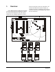
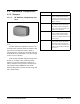
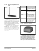
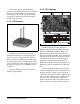
Table Of Contents
- Table of Contents
- 1 Overview
- 2 Installing the RF Gateway
- 2.1. Mounting the RF Gateway
- 2.2. Powering the RF Gateway
- 2.3. Wiring the RF Gateway to a CPC Site Controller (I/O Network)
- 2.4. Networking Gateways and Receivers (Token Ring Network)
- 3 Installing the RF Receiver
- 4 Installing the RF Sensor
- 5 Commissioning the RF Sensors
- 5.1. What is Commissioning?
- 5.2. Manual Entry Method
- 5.2.1. Entering the ID Numbers on the RF Gateway
- 1. Plug the Hand-Held Terminal into the HHT jack on the RF Gateway. The HHT should power up and d...
- 2. Press the DOWN ARROW key to display the Options menu.
- 3. Press the RIGHT ARROW, 1, DOWN ARROW, and DOWN ARROW to select the "Set Sensor ID" option and ...
- 4. In the ID Entry Method screen, press RIGHT ARROW, 1, DOWN ARROW, and DOWN ARROW to select the ...
- 5. The Enter Starting Board Address menu allows you to jump to Point 1 of the number of the "boar...
- 6. The commissioning screen for Point 1 of the board number you chose will be visible on the scre...
- 7. If you want this board and point input to be the temperature read by the RF Sensor, press 1 to...
- 8. The cursor should now be on the ID field. In the ID field, enter the number from the ID tag or...
- 9. Press the DOWN ARROW key again to move on to the next point on the board. Follow steps 6 throu...
- 5.2.1. Entering the ID Numbers on the RF Gateway
- 5.3. Service Pin Method
- 5.3.1. Setting up the RF Gateway to Receive ID Transmissions
- The RF Gateway board is designed to simulate four 16AI Analog Input boards, each of which has six...
- 1. Plug the Hand-Held Terminal into the HHT jack on the RF Gateway. The HHT should power up and d...
- 2. Press the DOWN ARROW key to display the Options menu.
- 3. Press the RIGHT ARROW, 1, DOWN ARROW, and DOWN ARROW to select the "Set Sensor ID" option and ...
- 4. In the ID Entry Method screen, press RIGHT ARROW, 2, DOWN ARROW, and DOWN ARROW to select the ...
- 5. The Enter Starting Board Address menu allows you to jump to Point 1 of the number of the "boar...
- 6. The commissioning screen for Point 1 of the board number you chose will be visible on the scre...
- 7. If you want this board and point input to be the temperature read by the RF Sensor, press 1 to...
- 8. The cursor should now disappear, and line 4 of the display will read "(PRESS SRVC PIN)." Press...
- 9. Press the DOWN ARROW key again to move on to the next point on the board. Follow steps 6 throu...
- 5.3.2. Hand-Held Terminal Screen Navigation Tips
- 5.3.1. Setting up the RF Gateway to Receive ID Transmissions
- 5.4. Verifying Successful Commissioning
- 5.5. Decommissioning a Sensor from the RF Gateway
- 6 Connecting Sensors to Einstein/REFLECS
- 7 Operation and Maintenance of the RF Sensor System
- 7.1. Status LEDs
- 7.2. Clean Switch Operation
- 7.3. Battery Life and Replacement
- 7.4. Viewing Status Using the Hand-Held Terminal
- For troubleshooting purposes, the RF Gateway allows you to view the temperature and digital input...
- 1. Plug the Hand-Held Terminal into the HHT jack on the RF Gateway. The HHT should power up and d...
- 2. Press the DOWN ARROW key to display the Options menu.
- 3. Press the RIGHT ARROW, and press 2 to view temperatures in degrees Fahrenheit or 3 to view tem...
- 4. The Enter Starting Board Address menu allows you to jump to Point 1 of the number of the "boar...
- 5. Point 1 of the board you selected in step 4 should be visible. This screen will display the ty...
- 7.4.1. Viewing Update Counts
- 7.5. RF Sensor Sleep Mode

4 • RF Sensor System I&O Manual 026-1702 Rev 0 10-30-00
The sensing element and transmitting
antenna for the RF Product Sensor are inside the
enclosure and may transmit to receivers up to
150 feet away. The sensor also has an internal
clean switch, which is activated by pressing a
button on the enclosure.
1.1.2. RF Receiver
The RF Receiver (P/N 837-3510) is an
antenna that mounts to the ceiling of the sales
area or on top of a refrigerated case. The RF
Receiver accepts transmissions from RF Ambi-
ent Temperature Sensors and RF Product Simu-
lators. It passes the sensor readings it receives to
the RF Gateway by way of an RS485 network
connection.
Up to six RF Receivers may be mounted
within a single building.
1.1.3. RF Gateway
The RF Gateway (P/N 810-3500) is an
RS485 peripheral board compatible with both
Einstein and REFLECS (RMCC, BEC, and
BCU) systems. The RF Gateway serves as an
interface between the RF Receivers, which send
messages from the sensors, and the area control-
lers, which use the sensor values for logging,
controlling, and alarming. Each Einstein or
REFLECS controller that will read values from
RF Sensors must be equipped with an RF Gate-
way.
Sensors and product simulators that will be
used by an Einstein must be “commissioned” in
the RF Gateway’s software. Once a sensor is
commissioned, the gateway then assigns the sen-
sor to a virtual "board and point" address. This
allows the area controller to tie application
inputs to RF Sensor values in the same way tra-
ditional 16AI board and point inputs are set up.
Figure 1-5 - RF Receiver
Figure 1-6 - RF Gateway Board