
User's Manual


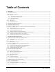
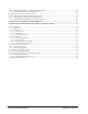
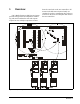
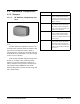
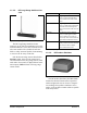
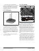
Table Of Contents
- Table of Contents
- 1 Overview
- 2 Installing the RF Gateway
- 2.1. Mounting the RF Gateway
- 2.2. Powering the RF Gateway
- 2.3. Wiring the RF Gateway to a CPC Site Controller (I/O Network)
- 2.4. Networking Gateways and Receivers (Token Ring Network)
- 3 Installing the RF Receiver
- 4 Installing the RF Sensor
- 5 Commissioning the RF Sensors
- 5.1. What is Commissioning?
- 5.2. Manual Entry Method
- 5.2.1. Entering the ID Numbers on the RF Gateway
- 1. Plug the Hand-Held Terminal into the HHT jack on the RF Gateway. The HHT should power up and d...
- 2. Press the DOWN ARROW key to display the Options menu.
- 3. Press the RIGHT ARROW, 1, DOWN ARROW, and DOWN ARROW to select the "Set Sensor ID" option and ...
- 4. In the ID Entry Method screen, press RIGHT ARROW, 1, DOWN ARROW, and DOWN ARROW to select the ...
- 5. The Enter Starting Board Address menu allows you to jump to Point 1 of the number of the "boar...
- 6. The commissioning screen for Point 1 of the board number you chose will be visible on the scre...
- 7. If you want this board and point input to be the temperature read by the RF Sensor, press 1 to...
- 8. The cursor should now be on the ID field. In the ID field, enter the number from the ID tag or...
- 9. Press the DOWN ARROW key again to move on to the next point on the board. Follow steps 6 throu...
- 5.2.1. Entering the ID Numbers on the RF Gateway
- 5.3. Service Pin Method
- 5.3.1. Setting up the RF Gateway to Receive ID Transmissions
- The RF Gateway board is designed to simulate four 16AI Analog Input boards, each of which has six...
- 1. Plug the Hand-Held Terminal into the HHT jack on the RF Gateway. The HHT should power up and d...
- 2. Press the DOWN ARROW key to display the Options menu.
- 3. Press the RIGHT ARROW, 1, DOWN ARROW, and DOWN ARROW to select the "Set Sensor ID" option and ...
- 4. In the ID Entry Method screen, press RIGHT ARROW, 2, DOWN ARROW, and DOWN ARROW to select the ...
- 5. The Enter Starting Board Address menu allows you to jump to Point 1 of the number of the "boar...
- 6. The commissioning screen for Point 1 of the board number you chose will be visible on the scre...
- 7. If you want this board and point input to be the temperature read by the RF Sensor, press 1 to...
- 8. The cursor should now disappear, and line 4 of the display will read "(PRESS SRVC PIN)." Press...
- 9. Press the DOWN ARROW key again to move on to the next point on the board. Follow steps 6 throu...
- 5.3.2. Hand-Held Terminal Screen Navigation Tips
- 5.3.1. Setting up the RF Gateway to Receive ID Transmissions
- 5.4. Verifying Successful Commissioning
- 5.5. Decommissioning a Sensor from the RF Gateway
- 6 Connecting Sensors to Einstein/REFLECS
- 7 Operation and Maintenance of the RF Sensor System
- 7.1. Status LEDs
- 7.2. Clean Switch Operation
- 7.3. Battery Life and Replacement
- 7.4. Viewing Status Using the Hand-Held Terminal
- For troubleshooting purposes, the RF Gateway allows you to view the temperature and digital input...
- 1. Plug the Hand-Held Terminal into the HHT jack on the RF Gateway. The HHT should power up and d...
- 2. Press the DOWN ARROW key to display the Options menu.
- 3. Press the RIGHT ARROW, and press 2 to view temperatures in degrees Fahrenheit or 3 to view tem...
- 4. The Enter Starting Board Address menu allows you to jump to Point 1 of the number of the "boar...
- 5. Point 1 of the board you selected in step 4 should be visible. This screen will display the ty...
- 7.4.1. Viewing Update Counts
- 7.5. RF Sensor Sleep Mode

1640 Airport Road, Suite 104
Kennesaw, GA 31044
Phone: (770) 425-2724
Fax: (770) 425-9319
ALL RIGHTS RESERVED.
The information contained in this manual has been carefully checked and is believed to be accurate. However, Com-
puter Process Controls, Inc. assumes no responsibility for any inaccuracies that may be contained herein. In no event will
Computer Process Controls, Inc. be liable for any direct, indirect, special, incidental, or consequential damages resulting
from any defect or omission in this manual, even if advised of the possibility of such damages. In the interest of continued
product development, Computer Process Controls, Inc. reserves the right to make improvements to this manual, and the
products described herein, at any time without notice or obligation.
FCC COMPLIANCE NOTICE
NOTE: This equipment has been tested and found to comply with the limits for a Class B digital device, pursuant to
Part 15 of the FCC Rules. These limits are designed to provide reasonable protection against harmful interference in a res-
idential installation. This equipment generates, uses, and can radiate radio frequency energy and, if not installed and used
in accordance with the instructions, may cause harmful interference to radio communications. However, there is no guar-
antee that interference will not occur in a particular installation. If this equipment does cause harmful interference to radio
or television reception, which can be determined by turning the equipment off and on, the user is encouraged to try and
correct the interference by one or more of the following measures:
-- Reorient or relocate the receiving antenna
-- Increase the separation between the equipment and the receiver
-- Connect the equipment into an outlet on a circuit different from that to which the receiver is connected
-- Consult the dealer or an experienced radio/TV technician for help
READ ALL INSTRUCTIONS CAREFULLY before attempting to install or operate the RF Sensor Sys-
tem.
SAVE THIS INSTRUCTION MANUAL — This instruction manual contains important operating instruc-
tions for the RF Sensor System.
Warning! FCC Regulations state that any unauthorized
changes or modifications to this equipment not expressly ap-
proved by the manufacturer could void the user's authoriza-
tion to operate this equipment.