
User's Manual


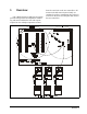
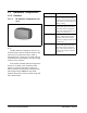
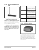
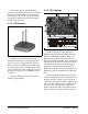
Table Of Contents
- Table of Contents
- 1 Overview
- 2 Installing the RF Gateway
- 2.1. Mounting the RF Gateway
- 2.2. Powering the RF Gateway
- 2.3. Wiring the RF Gateway to a CPC Site Controller (I/O Network)
- 2.4. Networking Gateways and Receivers (Token Ring Network)
- 3 Installing the RF Receiver
- 4 Installing the RF Sensor
- 5 Commissioning the RF Sensors
- 5.1. What is Commissioning?
- 5.2. Manual Entry Method
- 5.2.1. Entering the ID Numbers on the RF Gateway
- 1. Plug the Hand-Held Terminal into the HHT jack on the RF Gateway. The HHT should power up and d...
- 2. Press the DOWN ARROW key to display the Options menu.
- 3. Press the RIGHT ARROW, 1, DOWN ARROW, and DOWN ARROW to select the "Set Sensor ID" option and ...
- 4. In the ID Entry Method screen, press RIGHT ARROW, 1, DOWN ARROW, and DOWN ARROW to select the ...
- 5. The Enter Starting Board Address menu allows you to jump to Point 1 of the number of the "boar...
- 6. The commissioning screen for Point 1 of the board number you chose will be visible on the scre...
- 7. If you want this board and point input to be the temperature read by the RF Sensor, press 1 to...
- 8. The cursor should now be on the ID field. In the ID field, enter the number from the ID tag or...
- 9. Press the DOWN ARROW key again to move on to the next point on the board. Follow steps 6 throu...
- 5.2.1. Entering the ID Numbers on the RF Gateway
- 5.3. Service Pin Method
- 5.3.1. Setting up the RF Gateway to Receive ID Transmissions
- The RF Gateway board is designed to simulate four 16AI Analog Input boards, each of which has six...
- 1. Plug the Hand-Held Terminal into the HHT jack on the RF Gateway. The HHT should power up and d...
- 2. Press the DOWN ARROW key to display the Options menu.
- 3. Press the RIGHT ARROW, 1, DOWN ARROW, and DOWN ARROW to select the "Set Sensor ID" option and ...
- 4. In the ID Entry Method screen, press RIGHT ARROW, 2, DOWN ARROW, and DOWN ARROW to select the ...
- 5. The Enter Starting Board Address menu allows you to jump to Point 1 of the number of the "boar...
- 6. The commissioning screen for Point 1 of the board number you chose will be visible on the scre...
- 7. If you want this board and point input to be the temperature read by the RF Sensor, press 1 to...
- 8. The cursor should now disappear, and line 4 of the display will read "(PRESS SRVC PIN)." Press...
- 9. Press the DOWN ARROW key again to move on to the next point on the board. Follow steps 6 throu...
- 5.3.2. Hand-Held Terminal Screen Navigation Tips
- 5.3.1. Setting up the RF Gateway to Receive ID Transmissions
- 5.4. Verifying Successful Commissioning
- 5.5. Decommissioning a Sensor from the RF Gateway
- 6 Connecting Sensors to Einstein/REFLECS
- 7 Operation and Maintenance of the RF Sensor System
- 7.1. Status LEDs
- 7.2. Clean Switch Operation
- 7.3. Battery Life and Replacement
- 7.4. Viewing Status Using the Hand-Held Terminal
- For troubleshooting purposes, the RF Gateway allows you to view the temperature and digital input...
- 1. Plug the Hand-Held Terminal into the HHT jack on the RF Gateway. The HHT should power up and d...
- 2. Press the DOWN ARROW key to display the Options menu.
- 3. Press the RIGHT ARROW, and press 2 to view temperatures in degrees Fahrenheit or 3 to view tem...
- 4. The Enter Starting Board Address menu allows you to jump to Point 1 of the number of the "boar...
- 5. Point 1 of the board you selected in step 4 should be visible. This screen will display the ty...
- 7.4.1. Viewing Update Counts
- 7.5. RF Sensor Sleep Mode

Table of Contents • 1
Table of Contents
1 OVERVIEW................................................................................................................................................................... 1
1.1. S
YSTEM
D
ESCRIPTION
.................................................................................................................................................. 1
1.2. H
ARDWARE
C
OMPONENTS
........................................................................................................................................... 3
1.2.1. Sensors .................................................................................................................................................................. 3
1.2.1.1. RF Ambient Temperature Sensors...................................................................................................................................... 3
1.2.1.2. RF Long-Range Ambient Sensors...................................................................................................................................... 4
1.2.1.3. RF Product Simulator......................................................................................................................................................... 4
1.2.2. RF Receiver........................................................................................................................................................... 5
1.2.3. RF Gateway........................................................................................................................................................... 5
1.2.4. Hand-Held Terminal............................................................................................................................................. 6
2 INSTALLING THE RF GATEWAY........................................................................................................................... 7
2.1. M
OUNTING
THE
RF G
ATEWAY
..................................................................................................................................... 7
2.2. P
OWERING
THE
RF G
ATEWAY
..................................................................................................................................... 7
2.3. W
IRING
THE
RF G
ATEWAY
TO
A
CPC S
ITE
C
ONTROLLER
(I/O N
ETWORK
)................................................................ 8
2.3.1. Wire Connection ................................................................................................................................................... 8
2.3.2. Setting the Board Numbering Dip Switch............................................................................................................. 8
2.3.3. Setting the Baud Rate Dip Switch ......................................................................................................................... 9
2.3.4. Setting the RS485 I/O Termination Jumpers......................................................................................................... 9
2.4. N
ETWORKING
G
ATEWAYS
AND
R
ECEIVERS
(T
OKEN
R
ING
N
ETWORK
) ..................................................................... 10
2.4.1. Wiring the Token Ring Network to the Gateway................................................................................................. 10
2.4.2. Setting the Token Ring Network Termination Jumpers ...................................................................................... 10
3 INSTALLING THE RF RECEIVER......................................................................................................................... 11
3.1. M
OUNTING
AND
P
LACEMENT
OF
THE
RF R
ECEIVER
.................................................................................................. 11
3.1.1. Environmental Operating Conditions................................................................................................................. 11
3.1.2. Placement............................................................................................................................................................ 11
3.1.3. Mounting............................................................................................................................................................. 11
3.2. P
OWERING
THE
RF R
ECEIVER
.................................................................................................................................... 11
3.3. W
IRING
THE
RF R
ECEIVER
TO
A
CPC S
ITE
C
ONTROLLER
......................................................................................... 11
3.3.1. Wire Connection ................................................................................................................................................. 12
3.3.2. Setting the Token Ring Network Termination Jumpers ...................................................................................... 12
3.3.3. Setting the Receiver Numbering Dip Switch....................................................................................................... 12
3.3.4. Setting the Baud Rate Dip Switch ....................................................................................................................... 13
4 INSTALLING THE RF SENSOR.............................................................................................................................. 14
4.1. P
LACEMENT
OF
RF S
ENSORS
...................................................................................................................................... 14
4.1.1. RF (Short-Range) Ambient Sensor...................................................................................................................... 14
4.1.2. RF Long-Range Transmitter............................................................................................................................... 14
4.1.3. RF Product Simulator ......................................................................................................................................... 14
4.2. A
CTIVATION
............................................................................................................................................................... 14
4.2.1. Verifying Active State.......................................................................................................................................... 14
4.3. C
LEAN
S
WITCH
AND
D
EFROST
T
ERMINATION
W
IRING
.............................................................................................. 14
5 COMMISSIONING THE RF SENSORS.................................................................................................................. 16
5.1. W
HAT
IS
C
OMMISSIONING
? ........................................................................................................................................ 16
5.2. M
ANUAL
E
NTRY
M
ETHOD
......................................................................................................................................... 16
5.2.1. Entering the ID Numbers on the RF Gateway.................................................................................................... 17
5.3. S
ERVICE
P
IN
M
ETHOD
................................................................................................................................................ 18