
User's Manual


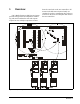
Table Of Contents
- Table of Contents
- 1 Overview
- 2 Installing the RF Gateway
- 2.1. Mounting the RF Gateway
- 2.2. Powering the RF Gateway
- 2.3. Wiring the RF Gateway to a CPC Site Controller (I/O Network)
- 2.4. Networking Gateways and Receivers (Token Ring Network)
- 3 Installing the RF Receiver
- 4 Installing the RF Sensor
- 5 Commissioning the RF Sensors
- 5.1. What is Commissioning?
- 5.2. Manual Entry Method
- 5.2.1. Entering the ID Numbers on the RF Gateway
- 1. Plug the Hand-Held Terminal into the HHT jack on the RF Gateway. The HHT should power up and d...
- 2. Press the DOWN ARROW key to display the Options menu.
- 3. Press the RIGHT ARROW, 1, DOWN ARROW, and DOWN ARROW to select the "Set Sensor ID" option and ...
- 4. In the ID Entry Method screen, press RIGHT ARROW, 1, DOWN ARROW, and DOWN ARROW to select the ...
- 5. The Enter Starting Board Address menu allows you to jump to Point 1 of the number of the "boar...
- 6. The commissioning screen for Point 1 of the board number you chose will be visible on the scre...
- 7. If you want this board and point input to be the temperature read by the RF Sensor, press 1 to...
- 8. The cursor should now be on the ID field. In the ID field, enter the number from the ID tag or...
- 9. Press the DOWN ARROW key again to move on to the next point on the board. Follow steps 6 throu...
- 5.2.1. Entering the ID Numbers on the RF Gateway
- 5.3. Service Pin Method
- 5.3.1. Setting up the RF Gateway to Receive ID Transmissions
- The RF Gateway board is designed to simulate four 16AI Analog Input boards, each of which has six...
- 1. Plug the Hand-Held Terminal into the HHT jack on the RF Gateway. The HHT should power up and d...
- 2. Press the DOWN ARROW key to display the Options menu.
- 3. Press the RIGHT ARROW, 1, DOWN ARROW, and DOWN ARROW to select the "Set Sensor ID" option and ...
- 4. In the ID Entry Method screen, press RIGHT ARROW, 2, DOWN ARROW, and DOWN ARROW to select the ...
- 5. The Enter Starting Board Address menu allows you to jump to Point 1 of the number of the "boar...
- 6. The commissioning screen for Point 1 of the board number you chose will be visible on the scre...
- 7. If you want this board and point input to be the temperature read by the RF Sensor, press 1 to...
- 8. The cursor should now disappear, and line 4 of the display will read "(PRESS SRVC PIN)." Press...
- 9. Press the DOWN ARROW key again to move on to the next point on the board. Follow steps 6 throu...
- 5.3.2. Hand-Held Terminal Screen Navigation Tips
- 5.3.1. Setting up the RF Gateway to Receive ID Transmissions
- 5.4. Verifying Successful Commissioning
- 5.5. Decommissioning a Sensor from the RF Gateway
- 6 Connecting Sensors to Einstein/REFLECS
- 7 Operation and Maintenance of the RF Sensor System
- 7.1. Status LEDs
- 7.2. Clean Switch Operation
- 7.3. Battery Life and Replacement
- 7.4. Viewing Status Using the Hand-Held Terminal
- For troubleshooting purposes, the RF Gateway allows you to view the temperature and digital input...
- 1. Plug the Hand-Held Terminal into the HHT jack on the RF Gateway. The HHT should power up and d...
- 2. Press the DOWN ARROW key to display the Options menu.
- 3. Press the RIGHT ARROW, and press 2 to view temperatures in degrees Fahrenheit or 3 to view tem...
- 4. The Enter Starting Board Address menu allows you to jump to Point 1 of the number of the "boar...
- 5. Point 1 of the board you selected in step 4 should be visible. This screen will display the ty...
- 7.4.1. Viewing Update Counts
- 7.5. RF Sensor Sleep Mode

2 • RF Sensor System I&O Manual 026-1702 Rev 0 10-30-00
5.3.1. Setting up the RF Gateway to Receive ID Transmissions................................................................................... 18
5.3.2. Hand-Held Terminal Screen Navigation Tips..................................................................................................... 19
5.4. V
ERIFYING
S
UCCESSFUL
C
OMMISSIONING
................................................................................................................. 19
5.5. D
ECOMMISSIONING
A
S
ENSOR
FROM
THE
RF G
ATEWAY
........................................................................................... 19
5.5.1. Decommissioning Manually Entered ID Numbers.............................................................................................. 19
5.5.2. Decommissioning ID Numbers Entered By Service Pin ..................................................................................... 20
6 CONNECTING SENSORS TO EINSTEIN/REFLECS........................................................................................... 21
7 OPERATION AND MAINTENANCE OF THE RF SENSOR SYSTEM.............................................................. 22
7.1. S
TATUS
LED
S
............................................................................................................................................................. 22
7.1.1. RF Sensors........................................................................................................................................................... 22
7.1.2. RF Receivers ....................................................................................................................................................... 22
7.1.2.1. The Status LED................................................................................................................................................................. 22
7.1.2.2. The RF LED...................................................................................................................................................................... 22
7.1.2.3. The Token Ring LED ....................................................................................................................................................... 22
7.1.3. RF Gateway......................................................................................................................................................... 23
7.1.3.1. The General Status LED ................................................................................................................................................... 23
7.1.3.2. The Alarm LED ................................................................................................................................................................ 23
7.1.3.3. RS485 I/O Network Status LED....................................................................................................................................... 23
7.1.3.4. Token Ring Network Status LED..................................................................................................................................... 23
7.2. C
LEAN
S
WITCH
O
PERATION
....................................................................................................................................... 23
7.2.1. Internal Clean Switch.......................................................................................................................................... 24
7.2.2. External Clean Switch......................................................................................................................................... 24
7.3. B
ATTERY
L
IFE
AND
R
EPLACEMENT
............................................................................................................................ 24
7.3.1. Reactivating the RF Sensor................................................................................................................................. 24
7.4. V
IEWING
S
TATUS
U
SING
THE
H
AND
-H
ELD
T
ERMINAL
.............................................................................................. 24
7.4.1. Viewing Update Counts....................................................................................................................................... 25
7.4.1.1. Resetting the Sensor Update Count.................................................................................................................................. 26
7.5. RF S
ENSOR
S
LEEP
M
ODE
........................................................................................................................................... 26