
User's Manual


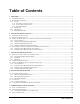
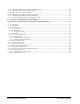
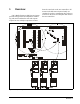
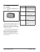
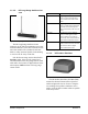
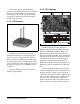
Table Of Contents
- Table of Contents
- 1 Overview
- 2 Installing the RF Gateway
- 2.1. Mounting the RF Gateway
- 2.2. Powering the RF Gateway
- 2.3. Wiring the RF Gateway to a CPC Site Controller (I/O Network)
- 2.4. Networking Gateways and Receivers (Token Ring Network)
- 3 Installing the RF Receiver
- 4 Installing the RF Sensor
- 5 Commissioning the RF Sensors
- 5.1. What is Commissioning?
- 5.2. Manual Entry Method
- 5.2.1. Entering the ID Numbers on the RF Gateway
- 1. Plug the Hand-Held Terminal into the HHT jack on the RF Gateway. The HHT should power up and d...
- 2. Press the DOWN ARROW key to display the Options menu.
- 3. Press the RIGHT ARROW, 1, DOWN ARROW, and DOWN ARROW to select the "Set Sensor ID" option and ...
- 4. In the ID Entry Method screen, press RIGHT ARROW, 1, DOWN ARROW, and DOWN ARROW to select the ...
- 5. The Enter Starting Board Address menu allows you to jump to Point 1 of the number of the "boar...
- 6. The commissioning screen for Point 1 of the board number you chose will be visible on the scre...
- 7. If you want this board and point input to be the temperature read by the RF Sensor, press 1 to...
- 8. The cursor should now be on the ID field. In the ID field, enter the number from the ID tag or...
- 9. Press the DOWN ARROW key again to move on to the next point on the board. Follow steps 6 throu...
- 5.2.1. Entering the ID Numbers on the RF Gateway
- 5.3. Service Pin Method
- 5.3.1. Setting up the RF Gateway to Receive ID Transmissions
- The RF Gateway board is designed to simulate four 16AI Analog Input boards, each of which has six...
- 1. Plug the Hand-Held Terminal into the HHT jack on the RF Gateway. The HHT should power up and d...
- 2. Press the DOWN ARROW key to display the Options menu.
- 3. Press the RIGHT ARROW, 1, DOWN ARROW, and DOWN ARROW to select the "Set Sensor ID" option and ...
- 4. In the ID Entry Method screen, press RIGHT ARROW, 2, DOWN ARROW, and DOWN ARROW to select the ...
- 5. The Enter Starting Board Address menu allows you to jump to Point 1 of the number of the "boar...
- 6. The commissioning screen for Point 1 of the board number you chose will be visible on the scre...
- 7. If you want this board and point input to be the temperature read by the RF Sensor, press 1 to...
- 8. The cursor should now disappear, and line 4 of the display will read "(PRESS SRVC PIN)." Press...
- 9. Press the DOWN ARROW key again to move on to the next point on the board. Follow steps 6 throu...
- 5.3.2. Hand-Held Terminal Screen Navigation Tips
- 5.3.1. Setting up the RF Gateway to Receive ID Transmissions
- 5.4. Verifying Successful Commissioning
- 5.5. Decommissioning a Sensor from the RF Gateway
- 6 Connecting Sensors to Einstein/REFLECS
- 7 Operation and Maintenance of the RF Sensor System
- 7.1. Status LEDs
- 7.2. Clean Switch Operation
- 7.3. Battery Life and Replacement
- 7.4. Viewing Status Using the Hand-Held Terminal
- For troubleshooting purposes, the RF Gateway allows you to view the temperature and digital input...
- 1. Plug the Hand-Held Terminal into the HHT jack on the RF Gateway. The HHT should power up and d...
- 2. Press the DOWN ARROW key to display the Options menu.
- 3. Press the RIGHT ARROW, and press 2 to view temperatures in degrees Fahrenheit or 3 to view tem...
- 4. The Enter Starting Board Address menu allows you to jump to Point 1 of the number of the "boar...
- 5. Point 1 of the board you selected in step 4 should be visible. This screen will display the ty...
- 7.4.1. Viewing Update Counts
- 7.5. RF Sensor Sleep Mode

2 • RF Sensor System I&O Manual 026-1702 Rev 0 10-30-00
1.1. Hardware Components
1.1.1. Sensors
1.1.1.1. RF Ambient Temperature Sen-
sors
The RF Ambient Temperature Sensor is an
enclosure with a built-in broadcast antenna. This
sensor may be mounted anywhere within a
refrigerated case, as long as it is within 150 feet
of an RF Receiver and within a clear line of sight
to the receiver’s antenna.
Four models of the RF Ambient Temperature
Sensor are available. Each model has either
internal or external temperature sensing ele-
ments, and either clean switch or defrost termi-
nation digital inputs. Table 1-1 lists all RF
Ambient Temperature Sensor models along with
their characteristics.
Figure 1-2 - Ambient Temperature Sensor (Internal Model
Shown)
Part Number Description
809-3542 RF Internal Ambient Sensor, w/
sensor element mounted inside
enclosure, and with a built-in clean
switch button for alarm suspension
during cleaning
809-3544 RF External Ambient Sensor, w/
external NSF-approved stainless
steel bullet sensor and neoprene
leads, with external leads for con-
nection to clean switch
809-3552 RF Internal Ambient Sensor, w/
sensor element mounted inside
enclosure and external leads for
connection to digital defrost termi-
nation sensor
809-3550 RF External Ambient Sensor, w/
external NSF-approved stainless
steel bullet sensor and neoprene
leads, with external leads for con-
nection to digital defrost termina-
tion sensor
Table 1-1 - RF Ambient Sensor Models