Installation and Configuration Guide
Trademark Notices Comtrol, NS-Link, and DeviceMaster are trademarks of Comtrol Corporation. Microsoft and Windows are registered trademarks of Microsoft Corporation. HyperTerminal is a registered trademark of Hilgraeve, Inc. Portions of SocketServer are copyrighted by GoAhead Software, Inc. Copyright © 2001. GoAhead Software, Inc. All Rights Reserved. Other product names mentioned herein may be trademarks and/or registered trademarks of their respective owners.
Table of Contents Installation Overview............................................................................................................7 Installation and Configuration .................................................................................................................. 7 Step 1: Hardware Installation ................................................................................................................... 7 Step 2: DeviceMaster 500 Configuration............................
Table of Contents Connecting Serial Devices .................................................................................................33 Connecting Devices..................................................................................................................................... 33 DB9 Serial Cables and Loopback Plugs ................................................................................................. 35 DB9 Loopback Plugs........................................................
Table of Contents Hardware Specifications ....................................................................................................59 Locating DeviceMaster 500 Specifications ............................................................................................ 59 Serial Communications .............................................................................................................................. 60 External Power Supply Specifications.........................................
Table of Contents vi - DeviceMaster 500 User Guide: 2000501 Rev.
Installation Overview This section provides an installation and configuration overview for the DeviceMaster 500. In addition, it provides links to download the latest files for the DeviceMaster 500 installation. Optionally, you can use the Software and Documentation CD to install the DeviceMaster 500. Installation and Configuration Use the following steps, which are discussed in detail in the subsequent sections, to install and configure the DeviceMaster 500.
Installation Overview Locating Software and Documentation You can access the appropriate software assembly, PortVision Plus, and the DeviceMaster 500 documentation from the CD shipped with the DeviceMaster 500. Optionally, if you know what you need for your installation, you can download the latest files using these internet links. If you are not sure what files are required for your installation, each installation and configuration procedure also provides links to the required files in this Guide.
Hardware Installation Installation Overview The DeviceMaster 500 enables communications with serial devices over an Ethernet network. The DeviceMaster 500 provides for remote management, configuration, and connectivity through its 10/100BASE–T Ethernet connection. Default Network Settings Use the links below to locate installation procedures for the following models: IP address: Ports DeviceMaster 500 Installation Procedure 192.168.250.
Hardware Installation 1-Port Installation Use the following procedure to install the DeviceMaster 500 1-Port. 1. Record the MAC address, model number, and serial number of the DeviceMaster 500 on the customer service label provided. You may need the MAC address during driver configuration. The model number, MAC address (starts with 00 C0 4E), and serial number are located on a label on the DeviceMaster 500. 2.
Hardware Installation Note: Align the power plugs properly. The scalloped side of the screw terminal power connector should be aligned with the scalloped side of the power jack on the unit. 6. Verify that the Status LED has completed the boot cycle and network connection for the DeviceMaster 500 is functioning properly using the table below. LED Descriptions The amber Status LED on the device is lit, indicating you have power and it has completed the boot cycle.
Hardware Installation 1-Port Embedded Installation Installing the DeviceMaster 500 1-Port Embedded system follows these basic steps: • Building the serial ribbon cable (below). • Mounting the Embedded 1-Port on Page 13 and installing light pipes. • Attaching the Network and Serial Cables on Page 14. • Connecting the Power and Verifying Installation on Page 14. Observe proper ESD techniques when handling the DeviceMaster 500.
Hardware Installation Mounting the Embedded 1-Port Use the following procedure to mount the DeviceMaster 500 1-Port Embedded with the 5-30VDC power supply. Observe proper ESD techniques when handling the DeviceMaster 500. Caution 1. Carefully remove the DeviceMaster 500 from the anti-static bag, following standard electrostatic device handling procedures.
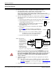
Hardware Installation 4. Optionally, attach the light pipes. The following light pipes have been tested and found to function; Bivar, Inc. (P/N:LP-230) and Ledtronics, Inc. (P/N:LTP003-0CW-001). After mounting the DeviceMaster 500, you are ready to connect the cables. Attaching the Network and Serial Cables Use the following procedure to attach the serial ribbon and Ethernet cables. For a larger illustration of the system, see Notices on Page 62. 1.
Hardware Installation 3. Plug the screw terminal power connector into JP1 on the DeviceMaster 500 by aligning the scalloped sides. 4. Apply power to the DeviceMaster 500. LEDs 5. Verify the Status LED has completed the boot cycle and network connection for the DeviceMaster 500 is functioning properly using the table below. JP1 The LEDs are located between the RJ45 connector and the power terminal block.
Hardware Installation 4-Port Installation Use the following procedure to install the DeviceMaster 500 4-port. 1. Record the MAC address, model number, and serial number of the DeviceMaster 500 unit on the customer service label provided. You may need the MAC address during driver configuration. The serial number and MAC address (starts with 00 C0 4E) are located on a label on the DeviceMaster 500. 2.
Hardware Installation 5. Verify that the PWR LED has completed the boot cycle and network connection for the DeviceMaster 500 is functioning properly using the table below. LED Descriptions LED on the front panel of the DeviceMaster 500 is lit, indicating you have power and it has completed the boot cycle. PWR Note: The PWR LED flashes while booting and it takes approximately 15 seconds for the Bootloader to complete the cycle.
Hardware Installation Replacing Hardware Follow the appropriate procedure to replace DeviceMaster 500 with another DeviceMaster 500 in an existing configuration. Device Programmed with IP Address Use this procedure to replace hardware if the existing device is programmed for use with an IP address. 1. Configure the IP address in the new DeviceMaster 500. 2. Remove the old unit and attach a new or spare DeviceMaster 500. 3. Connect the new DeviceMaster 500 to the network hub or server NIC. 4.
Initial Configuration There are several ways to configure network information. Comtrol Technical Support recommends connecting the DeviceMaster 500 to a PC or laptop running Windows® and installing PortVision Plus for initial configuration.
Initial Configuration 4. Go to Step 4 in the next section, Configuring the Network Settings, to program the DeviceMaster 500 network settings. If you need additional information about PortVision Plus, refer to the Help system. Configuring the Network Settings Use the following procedure to change the default network settings on the DeviceMaster 500 for your network.
Initial Configuration 5. Optionally, rename the DeviceMaster 500 in the Device Name field. 6. Change the DeviceMaster 500 network properties as required for your site. • If you want to run the DeviceMaster 500 using the MAC addressing scheme, click Disable IP. • To use the DeviceMaster 500 with DHCP, click DHCP IP, and make sure that you provide the MAC address of the device to the network administrator.
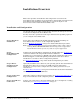
Initial Configuration Checking the SocketServer Version SocketServer is integrated in the firmware that comes pre-installed on your DeviceMaster 500 platform, which provides an interface to TCP/IP socket mode configuration and services. Comtrol recommends verifying that your DeviceMaster 500 contains the latest SocketServer version before installing the device driver or configuring socket ports to avoid installation problems.
Initial Configuration Uploading SocketServer Use this section to upload a new version of SocketServer on the DeviceMaster 500 using PortVision Plus. Technical Support recommends updating SocketServer before initial device driver installation to avoid configuration problems. 1. Make sure that you have located or downloaded the latest SocketServer version. 2. Right-click the DeviceMaster 500 for which you want to update, click Upload Firmware, browse to the SocketServer .bin file, and then click Open. 3.
Initial Configuration 24 - Initial Configuration DeviceMaster 500 User Guide: 2000501 Rev.
Device Driver Installation Before installing the NS-Link device driver, the following conditions must be met: • The DeviceMaster 500 is connected to the network and powered on (Hardware Installation on Page 9) • The network information has been configured in the DeviceMaster 500 (Configuring the Network Settings on Page 20) • If this is the initial device driver installation, verify that the DeviceMaster 500 contains the latest version of SocketServer (Checking the SocketServer Version on Page 22) Af
Device Driver Installation 3. Go to the appropriate procedure to install the driver. The device driver for Windows installation follows these steps for each DeviceMaster 500. If you have multiple DeviceMaster 500s, you must repeat this process for each DeviceMaster 500.
Device Driver Installation Windows XP and Windows Server 2003: NS-Link Installation After locating the latest driver (Page 25) and extracting the files, use this procedure to install and configure the NS-Link device driver for your DeviceMaster 500. 1. From the Start button, click Control Panel and then double-click Add Hardware. 2. Click Next when the Add Hardware Wizard starts. 3. Click Yes, I have already connected the hardware and then Next. 4.
Device Driver Installation Windows 2000: NSLink Installation After locating the latest driver (Page 25) and extracting the files, use this procedure to install and configure the NS-Link device driver for your DeviceMaster 500. 1. Click Start, Settings, and Control Panel, and then double-click Add/Remove Hardware. 2. Click Next. 3. Click Add/Troubleshoot a device and then Next. 4. Highlight Add a new device and click Next. 5. Click No, I want to select the hardware from a list and then Next. 6.
Device Driver Installation Configuring the NS-Link Driver for Windows The DeviceMaster 500 must be connected to the local network segment or directly to a NIC on the host system to operate in MAC mode to perform the following procedure. 1. Access the Properties page for the DeviceMaster 500. a. Right-click My Computer or Computer, click Manage, and then highlight Device Manager. b.
Device Driver Installation Configuring COM Port Properties for Windows The following is a COM port properties configuration overview. Use the NS-Link User Guide for Windows (also available on the CD) or the NS-Link Help system for detailed configuration information. 1. Access the Properties page for the DeviceMaster 500. a. Right-click My Computer or Computer, click Manage, and then highlight Device Manager. b.
Device Driver Installation Completing the SICK LMS Scanner Installation Use the following procedure to complete a SICK LMS Scanner installation. 1. Connect the LMS Scanner to the DeviceMaster 500 port that you configured using the RS-422 cable (or optionally the RS-232 cable if you do not want to use the 500K rate) to the scanner. Note: Do not connect the power on the LMS scanner at this time. 2. Open PortVision Plus (Start/Programs/Comtrol/PortVision Plus/PortVision Plus). 3.
Device Driver Installation 7. Set WCOM2 to view Hex data by selecting the View/Hex Display menu option. Hex Display displays a check when selected. Note: All the communications with the scanner are in Hex format. 8. Connect the power cord of the scanner to a power source. When the scanner displays a green light, you should see a message on the WCom2 window. 9. Use the Port/Send ASCII / HEX String menu to send the appropriate hex commands using LMS scanner manual to perform these steps: a.
Connecting Serial Devices This section discusses connecting your serial devices to the DeviceMaster 500. In addition, it provides you with information to build serial cables and loopback connectors to test the serial ports. Connecting Devices Use this procedure to connect asynchronous serial devices to the DeviceMaster 500 ports. Caution Make sure that you have configured the ports for the correct communications mode before connecting any devices. The default mode in the NS-Link drivers is RS-232.
Connecting Serial Devices 1-Port Embedded LEDs When lit, the amber Status LED (D1) on the DeviceMaster 500 indicates the devices is fully powered and has completed the boot cycle. Status Note: The Status LED flashes for approximately 15 seconds while booting. When the Bootloader completes the cycle, the LED has a solid, steady light that blinks approximately every 30 seconds. Link/Act When lit, the red Link/Act LED (D2) indicates a working Ethernet connection.
Connecting Serial Devices DB9 Serial Cables and Loopback Plugs You can build your own null-modem or straight-through DB9 serial cables using the following subsections. DB9 Connector Pinouts Pin 1 2 3 4 5 6 7 8 9 RS-232 DCD RxD TxD DTR GND DSR RTS CTS RI RS-422 Not used RxDTxDNot used Not used† Not used TxD+ RxD+ Not used RS-485 Not used Not used TxD/RxDNot used Not used† Not used TxD/RxD+ Not used Not Used † Pin 5 is tied to ground on the board, but is not used in the cable.
Connecting Serial Devices DB9 Null-Modem Cables (RS-232) Use the following figure if you need to build an RS-232 null-modem cable. A nullmodem cable is required for connecting DTE devices. Female DeviceMaster DB9 DB9 DB25 RJ45 Signal Pins TxD 3 RxD 2 RTS 7 CTS 8 DSR 6 1 DCD DTR 4 GND 5 Pins Pins Pins Signal RxD 2 3 5 TxD 3 2 4 CTS 8 5 8 RTS 7 4 1 DTR 4 20 2 DCD 1 8 6 DSR 6 6 7 GND 5 7 3 Note: You may want to purchase or build a straight-through cable and purchase a null-modem adapter.
Socket Port Configuration This section discusses the following topics: • SocketServer Overview • SocketServer Versions on Page 40 • Accessing Socket Configuration on Page 39 SocketServer Overview SocketServer is the name of the TCP/IP socket web page that is integrated in the firmware that comes pre-installed on your DeviceMaster 500.
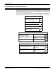
Socket Port Configuration SocketServer Architecture TCP/IP socket mode operation is used to connect serial devices with an application that supports TCP/IP socket communications addressing. DeviceMaster PC or Mainframe IP socket application Ethernet Hub LAN/WAN Ethernet Hub Serial Device TCP/IP Socket Mode Serial tunneling mode is used to establish a socket connection between two DeviceMaster 500s through an ethernet network.
Socket Port Configuration Accessing Socket Configuration There are several ways to access the socket configuration pages (SocketServer or NS-Link). Use the method that fits your environment best. Web Browser • Web Browser • PortVision Plus To access the socket configuration page for the DeviceMaster 500 using a web browser, follow this procedure. 1. Start your web browser. 2. Enter the IP address of the DeviceMaster 500 in the URL field.
Socket Port Configuration SocketServer Versions The SocketServer Overview discusses the that the default SocketServer web page is the same as the NS-Link web page. If the NS-Link driver is not running (not installed or disabled), the default SocketServer loads when you open a web browser session. Your SocketServer or NS-Link version may be different than these examples. 40 - Socket Port Configuration DeviceMaster 500 User Guide: 2000501 Rev.
Managing the DeviceMaster 500 This section discusses the following DeviceMaster 500 maintenance procedures: • Rebooting the DeviceMaster 500 • Uploading SocketServer to Multiple DeviceMaster 500s on Page 42 • Configuring Multiple DeviceMaster 500s Network Addresses on Page 42 • Using Configuration Files on Page 43 • Managing Bootloader on Page 44, which also discusses checking the Bootloader version and downloading the latest Bootloader • Adding a DeviceMaster 500 to an Existing Installation on
Managing the DeviceMaster 500 Uploading SocketServer to Multiple DeviceMaster 500s If the Windows NS-Link driver has been installed, make sure that the driver is disabled through the Device Manager before uploading SocketServer. 1. If you have not done so, install PortVision Plus (Installing PortVision Plus on Page 19) and Scan the network. 2.
Managing the DeviceMaster 500 Using Configuration Files If you are deploying multiple DeviceMaster 500 units that share common values, you can save the configuration file (.dmc) from the Main or Configure Device screens in PortVision Plus and load that configuration onto other DeviceMaster 500 units. If you save a configuration file from the Main or Configure Device screen, you can choose what properties you want saved. Use this procedure to save a configuration file using the Main screen. 1.
Managing the DeviceMaster 500 Managing Bootloader Bootloader refers to the operating system that runs on the DeviceMaster 500 hardware during the power on phase, which then loads SocketServer. Note: Typically, you should not update the Bootloader unless advised to do so by Comtrol Technical Support. There are several methods and tools that you can use to check the Bootloader version or update the Bootloader.
Managing the DeviceMaster 500 3. Right-click the DeviceMaster 500 for which you want to update, click Upload Firmware, browse to the Bootloader .bin file, and then click Open. 4. Click Yes to the Upload Firmware message that warns you that this is a sensitive process. 5. Click Ok to the second Upload Firmware message and then click Refresh until the Bootloader version displays in the List View pane, which should show the new version. DeviceMaster 500 User Guide: 2000501 Rev.
Managing the DeviceMaster 500 Adding a DeviceMaster 500 to an Existing Installation Use this procedure to add another DeviceMaster 500 to an existing configuration. 1. Install the DeviceMaster 500 to an Ethernet hub or server NIC. If necessary, see Hardware Installation on Page 9. Note: Technical support recommends installing and testing one DeviceMaster 500 at a time when installing multiple DeviceMaster 500s.
Managing the DeviceMaster 500 6. Transfer all cabling from the old DeviceMaster 500 to the new DeviceMaster 500. 7. Restart the host PC. Restoring Serial Port Settings Use the web page and/or the NS-Link device driver for Windows to restore the serial port settings to their default values. The NS-Link serial port settings are independent of the socket serial port settings on the web page.
Managing the DeviceMaster 500 48 - Managing the DeviceMaster 500 DeviceMaster 500 User Guide: 2000501 Rev.
RedBoot Procedures Use this section as a reference if you want to perform tasks in Redboot. Typically, most of these procedures can be performed using PortVision Plus. Overview You can use a serial connection between Port 1 on the DeviceMaster 500 and a COM port on a PC. If you plan on using the serial method, you will need a null modem cable and a terminal program installed and configured on the PC.
RedBoot Procedures 7. Go to the appropriate task: Establishing a Telnet Connection • Determining the Network Settings on Page 51 • Configuring the Network Settings on Page 51 • Determining the Bootloader Version on Page 52 • Resetting the DeviceMaster 500 on Page 52 • Uploading Firmware on Page 53 • Configuring Passwords on Page 56 • Redboot Command Overview on Page 57. Use the following procedure to telnet to the DeviceMaster 500. 1.
RedBoot Procedures Determining the Network Settings If you are not sure what the network information is on a DeviceMaster 500, you can perform the following procedure. 1. Establish communications with the DeviceMaster 500 using the serial (Page 49) method. Default Network Settings 2. IP address: 192.168.250.250 Subnet mask: 255.255.0.0 Gateway address: 192.168.250.1 At the RedBoot prompt, type ip. RedBoot>dis Loading disabled RedBoot> ip IP Config: IpAddr 192.168.250.250 IpMask 255.255.0.0 IpGate 192.168.
RedBoot Procedures Determining the Bootloader Version Use the following procedure to determine what Bootloader version is loaded in the DeviceMaster 500. 1. Establish communications with the DeviceMaster 500 using the serial (Page 49) or telnet (Page 50) method. 2. At the RedBoot prompt, type version. RedBoot> version ********************************************* ** ** Comtrol DeviceMaster Bootloader Version 3.
RedBoot Procedures Uploading Firmware Use the appropriate procedure for your environment: • Serial Method on Page 53 • Telnet Method on Page 55 Note: Optionally, you can install PortVision Plus on a Windows system on the network and upload firmware. PortVision Plus is the recommended method for uploading firmware. Serial Method The procedure for updating the Bootloader and SocketServer are the same, but the .bin files are unique. 1. Verify that you have the .
RedBoot Procedures e. Click Send. The file name in this screen shows the Bootloader. 10. When the RedBoot> prompt appears (after approximately one minute for the Bootloader and approximately three minutes for SocketServer), type go. CCCCCCRaw load done: 542721 bytes read Address range: 00000000-00084800, Entry point: 00000000, xyzModem - CRC mode, 4241(SOH)/0(STX)/0(CAN) packets, 8 tries RedBoot> go ... Erase from 0x05030000-0x050c0000: ......... ... Program from 0x00000000-0x00084801 at 0x05060000: ...
RedBoot Procedures Telnet Method Use the following procedure to update the Bootloader or SocketServer with telnet to the DeviceMaster 500. Note: A TFTP server is required to perform firmware updates using Redboot. 1. Verify that you have the .bin file (Locating Software and Documentation on Page 6). 2. Open a telnet session, type reset, and close the session. 3. Open a new telnet session and enter the DeviceMaster 500 IP address. $ telnet 192.168.250.250 Trying 192.168.250.250... Connected to 192.168.250.
RedBoot Procedures If uploading SocketServer: a. At the RedBoot> prompt, type: fis list and press Enter. RedBoot> fis list Name FLASH addr Mem addr Length Entry point FIS_directory 0x053F0000 0x053F0000 0x00010000 0x00000000 default 0x05030000 0x00000000 0x00090000 0x00000000 RedBoot> Note: You should see file information for a file called default. If you do not see this file, repeat the process starting with Step 7. b. Reset the DeviceMaster 500 by typing reset at the RedBoot> prompt.
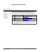
RedBoot Procedures Redboot Command Overview The following table is an overview of Redboot commands available. You can access the list of commands online by entering help and pressing the Enter key. For more detailed information, see the Redboot User’s Guide that is located on the Comtrol product CD or download it from the web. RedBoot Commands Sets or displays web authentication. The default is set to none, which means that there is no authentication required to access the web server.
RedBoot Procedures 58 - RedBoot Procedures DeviceMaster 500 User Guide: 2000501 Rev.
Hardware Specifications The following subsections contain specifications and safety notices for the DeviceMaster 500 family. • Locating DeviceMaster 500 Specifications • Serial Communications on Page 60 • External Power Supply Specifications on Page 61 - • Power Supply for the 1-Port on Page 61 Note: Use the specifications to provide a power supply for the embedded version. Power Supply for the 4-Port on Page 61 Notices on Page 62 RoHS compliant products conform to EU Directive 2002/95/EC.
Hardware Specifications Serial Communications This table provides DeviceMaster 500 serial communications specifications. Serial Communications Interface RS-232, RS-422, and RS-485 Serial connector types: 1-Port standard 1-Port embedded 4-Port DB9 Male Header, IDC10 DB9 Baud rate/port Receive buffer Transmit buffer 9600, 57.
Hardware Specifications External Power Supply Specifications This subsection discusses information that you may need if you wish to use your own external power supplies Power Supply for the 1-Port • Power Supply for the 1-Port on Page 61 • Power Supply for the 4-Port on Page 61 This table provides specifications for the power supply shipped with the DeviceMaster 500 1-port.
Hardware Specifications Notices Radio Frequency Interference (RFI) (FCC 15.105) Labeling Requirements (FCC 15.19) This equipment has been tested and found to comply with the limits for Class A digital devices pursuant to Part 15 of the FCC Rules. This equipment generates, uses, and can radiate radio frequency energy, and if not installed and used in accordance with the instruction manual, may cause harmful interference to radio communications.
Troubleshooting and Technical Support This section contains troubleshooting information for your DeviceMaster 500. You should review the following subsections before calling Technical Support because they will request that you perform many of the procedures or verifications before they will be able to help you diagnose a problem.
Troubleshooting and Technical Support • Verify that the network IP address, subnet mask, and gateway is correct and appropriate for the network. If IP addressing is being used, the system should be able to ping the DeviceMaster 500. • Verify that the IP address programmed into the DeviceMaster 500 matches the unique reserved IP configured address assigned by the system administrator. • If using DHCP, the host system needs to provide the subnet mask and gateway.
Troubleshooting and Technical Support General Condition Explanation/Action The NS-Link driver uses Port 4606 (11FE h) to communicate with the DeviceMaster 500. Can ping the Comtrol device, but cannot open the ports from a remote location. When using a “sniffer” to track NS-Link packets, filtering for Port 4606 will easily track the packet.
Troubleshooting and Technical Support General Condition Explanation/Action The problem is caused by a L2 bridging feature called Spanning Tree Algorithm (STA) in the Switch. This feature is enabled by default in some switches. This features causes time-out problems on certain L2 protocols, such as our MAC mode. Resolution: There will be no firmware fix for this problem. Only one of the following fixes is required for resolution. 1. Disable STA in the switch. 2. Enable STA fast forwarding on the port. 3.
Troubleshooting and Technical Support Daisy-Chaining DeviceMaster 500 4-Port Units The DeviceMaster 500 4-port models with external power supplies follow the IEEE specifications for standard Ethernet topologies. When using the UP and DOWN ports, the DeviceMaster 500 4 is classified as a switch. When using the UP port only, it is a simple end node device.
Troubleshooting and Technical Support Technical Support If you are using an NS-Link driver for a Windows system, you should review the troubleshooting section in the NS-Link User Guide for Windows (Page 8) before contacting Technical Support. It contains troubleshooting procedures that you should perform before contacting Technical Support since they will request that you perform, some or all of the procedures before they will be able to help you diagnose your problem.
Index Symbols #!DM command 49 Numerics 100 LED 1-port embedded 15 standard 11 4-port 17 1-port installation embedded 12 standard 10 4-port installation 16 A add new DeviceMaster to system 17, 46 address MAC format 29 administrator password Redboot 57 agency notices 62 associating MAC address in NS-Link 29 auth command 57 B baud rate/port 60 boardrev command 57 boot cycle 1-port embedded 15 standard 11 4-port 17 Bootloader downloading the latest 8 updating 44 version 52 building cables null-modem DB9 36 e
Index devices how to connect 33 how to daisy-chain 4-port models 16 DIN rail installation 10 removing 10 dis command 49 disable loading 57 disable command 57 disable DeviceMaster #!DM command 49 display Bootloader timeout 57 hex dump of memory range 57 IP address 57 MAC address 57 model number 57 Redboot version 57 telnet 57 downloading latest software and documentation 8 drivers installation Windows 2000 28 Windows Server 2003 27 Windows Vista 26 Windows XP 27 dump command 57 Duplex 1-port embedded 15 Dup
Index M MAC address associating in NS-Link 29 format 29 mac command 57 machine cache manage 57 memory range display hex dump 57 model command 57 N network configuration telnet 51 configuration with PortVision Plus 20 default values 60 how to connect to 9 protocols 60 network information how to determine 51 NS-Link associating MAC address 29 installation Windows 2000 28 Windows Server 2003 27 Windows Vista 26 Windows XP 27 SocketServer 40 NS-Link drivers 8 null-modem cables 36 DB9 36 O overview installation
Index terse command 57 TFTP load command 57 timeout command 57 troubleshooting 63 tunneling serial 38 U updating Bootloader 44 User Guides downloading latest 8 V version Bootloader 52 SocketServer 40 version command 57 W Windows 2000 NS-Link installation 28 Windows Server 2003 NS-Link installation 27 Windows Vista NS-Link installation 26 Windows XP NS-Link installation 27 X Xmodem load command 57 72 - DeviceMaster 500 User Guide: 2000501 Rev.