
Instruction Manual


10 - DeviceMaster 500 User Guide: 2000501 Rev. A Hardware Installation
Hardware Installation
1-Port Installation
Use the following procedure to install the DeviceMaster 500 1-Port.
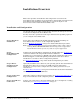
1. Record the MAC address, model number, and serial number of the
DeviceMaster 500 on the customer service label provided.
You may need the MAC address during driver configuration. The model
number, MAC address (starts with 00 C0 4E), and serial number are located on
a label on the DeviceMaster 500.
2. Place the DeviceMaster 500 1-Port on a stable surface and skip to Step 3
or
optionally mount the DeviceMaster 500 using the mounting flanges or DIN
rail adapters.
3. Connect the DeviceMaster 500 port labeled 10/100 ETHERNET to the same
Ethernet network segment as the host PC using a standard network cable.
If you plan on using the NS-Link device driver, make sure that you do
not connect RS-422/485 devices until the appropriate port interface
type has been configured in the driver. The NS-Link default port
setting is RS-232.
4. Apply power to the DeviceMaster 500 using the appropriate procedure for
your power supply.
Note: The supported input voltage 5-30VDC is printed on the DeviceMaster
500. If you want to replace the power supply that is shipped with the
DeviceMaster 500 and use your own power supply, see Power Supply for
the 1-Port on Page 61.
5. Connect the power supply to the DeviceMaster 500 and to a power outlet.
a. Pick up the DeviceMaster 500 so that the front of the device is facing you.
b. Pick up a DIN rail clip. (The three tines should be on top
and the M4 label should face you.)
c. Slide the DIN rail clip behind the DeviceMaster 500 and
line it up with one of the screw holes on the
DeviceMaster 500.
d. Insert a screw into the hole and tighten with a Phillips
screwdriver.
e. Repeat Steps b
through d with the second DIN rail
clip. Make sure the screws on both DIN rail clips line
up.
Note: If you need to remove the DeviceMaster 500 from
the DIN rail, exert pressure on the backside of
the tabs at the bottom of both DIN rail clips.
f. Attach the DeviceMaster 500 to the DIN rail.
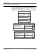
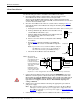
Note: For optimal
operation, make
sure that the device
is mounted in a
vertical orientation
with a minimum of
1.0” space on either
side and a
minimum of 4.5”
clearance from the
center of the rail to
any device or wire trough above the unit and a minimum of 5.0” below.
M4
DIN Rail
Clip
Side View
Press here
4.5”
5.0”
1.0”
1.0”
Front View
DeviceMaster 500
Caution