Conceptronic (Wireless) Internet Camera CNETCAM / C54NETCAM User’s Guide Version 1.
Table of Contents 1. Package Contents 2. System Requirements 2.1 Networking 2.2 Accessing the Camera 3. Explanation of the Controls 4. Hardware Installation 4.1 Attaching the Camera to the Stand 4.2 Connecting the Ethernet cable 4.3 Attaching the Powersupply 5. Security 6. Using the (Wireless) Internet Camera through the webbrowser 6.1 6.2 6.3 6.4 6.5 6.6 6.7 6.
1. Package Contents • • • • • • Conceptronic CNETCAM / C54NETCAM Camera stand which can be used for wall mount Power supply, 5V DC, 2.5A Antenna (Only with the C54NETCAM) CD-ROM with software and manual Quick Installation Guide 2. System Requirements 2.1. Networking • Local Area Network : 10Base-T Ethernet or 100Base-TX Fast Ethernet. • Wireless Local Area Network : IEEE 802.11g Wireless LAN. 2.2.
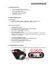
1. Screw Hole Located on the top/bottom panel of the camera, the screw hole is used to connect the camera stand onto the camera by attaching the screw head on the camera stand into the screw hole of the camera. 2. Power and Link LED The Power LED is positioned on the right side of the Wireless Internet Camera’s lens while facing the Wireless Internet Camera. A steady BLUE light confirms that the Wireless Internet Camera is powered on.
4. Hardware Installation 4.1. Attaching the Camera to the Stand The Wireless Internet Camera comes with a camera stand (optional) with a swivel ball screw head that can be attached to the Wireless Internet Camera's bottom screw hole. Attach the camera stand to the Wireless Internet Camera and station it for your application. There are three holes located in the base of the camera stand allowing the Wireless Internet Camera to be mounted on the ceiling or any wall securely. 4.2.
. Using the (Wireless) IP Camera through the webbrowser You can access and manage the Wireless Internet Camera through: 1) a web browser, and 2) the enclosed software IPView SE. This chapter describes the Web Configuration Utility, and provides the instructions on using the camera with a web browser. 6.1. Web Configuration Utility The (Wireless) Internet Camera can be configured with the Setup Wizard, or through its built-in Web-based Configuration.
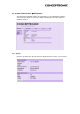
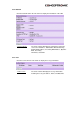
6.3. System Administration Æ Management The Management window contains the information of your configuration. Click the items in the left column to view your settings, including: System, Video, Wireless, Network, and User. 6.3.1. System Click the System item in the left column to display the device status of your camera.
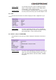
- Device Status: - Ethernet Status: The information about the camera, including the Camera Name, Location, Model, Firmware Version, MAC Address and IP Address, can be found in this field. You can monitor the networking status in this field, including the Link (network connection), Speed, and the Duplex mode. 6.3.2. Video Click the Video item in the left column to display the video configuration of your camera.
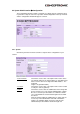
6.3.4. Network Click the Network item in the left column to display the information of the LAN. - Network Status: The items in this field display the information of the LAN, such as the IP Address, SubnetMask, Default Gateway, Primary DNS Address, Secondary DNS Address, Dynamic DNS, Secondary HTTP Port, and UPnP. 6.3.5. User Click the User item in the left column to display the user(s) information.
6.4 System Administration Æ Configuration The Configuration window contains commands for settings that are required to input key details to setup the camera for operation. Click Configuration in the top menu bar and the configuration window will appear as below: 6.4.1. System Click the System item in the left column to setup the basic configuration of your camera. - Camera Name: - Location: - Admin: This field is used to enter a descriptive name for the device.
- LED Control: • Normal • OFF • Dummy (printable ASCII) characters. It is highly recommended to set the Admin ID and Admin Password as soon as possible to enable security option for the (Wireless) Internet Camera to function. This option allows user to setup the LED illumination as desired. This feature provides the flexibility when surveillance activity is ON. There are three options as follows: Power - Steady On of the LED indicator. Link - Steady On of the LED indicator.
Click the Wireless item in the left column to setup the wireless LAN configuration of your camera. - Connection Mode: - SSID: - Wireless Channel: Use this option to determine the type of wireless communication for your camera. There are two choices of Infrastructure mode and Ad-Hoc mode. The default setting is Infrastructure. The SSID (Service Set Identifier) is the name assigned to the wireless network.
mode. Select the appropriate channel from the list provided depending on the regulatory region where the unit is sold. The default setting is at channel 11. - Transmission Rate: Select the data transmit rate from this pull-down menu. The default setting is Fully Automatic. - WEP Encryption WEP Encryption: Wireless network communications can be intercepted easily. WEP (Wired Equivalent Privacy) is an encryption method specified by the IEEE 802.
6.4.4. Network Click the Network item in the left column to setup the LAN configuration of your camera. This field provides your with three options to select the IP Address Mode: - Fixed IP You can select this option and enter the IP address directly. The default settings are: IP Address – 192.168.0.20 Subnet Mask – 255.255.255.0 Default Gateway – 0.0.0.0 - Dynamic Address (DHCP) If your network uses the DHCP server, select this option.
- Second HTTP Port : - UPnP: The default port for communication is via port 80, and you can change it according to your network configuration. Select Enable from the option and enter the desired port number in the following box. UPnP is the architecture for pervasive peer-to-peer network connectivity of intelligent appliances, wireless devices, and PCs of all form factors. Check the Enable option to enable the function of your camera. 6.4.5.
6.4.6. DateTime Click the DateTime item in the left column to setup time and date for your camera, providing correct information for the remote users who might be thousands of miles away from the camera’s location. You can set up time and date manually or automatically by selecting the Synchronized with Time Server option. - Synchronized with Time Server: Select this option and the time will be based on GMT setting. The time will be synchronized every 10 minutes.
6.4.7. Upload Click the Upload item in the left column to setup configuration for FTP server, time schedule and manual operation. - Host Address: - Port Number: - User Name: - Password: - Directory Path: - Passive Mode: - Time Schedule: - Schedule: The IP Address of the target FTP server. The standard port number for the FTP server is Port 21, and it’s also the default setting. If the FTP server uses a specific port, please confirm the IT manager. Enter the user name in this field.
- Video Frequency: - Base File Name: - File: - Manual Operation: There are two ways to set the video frequency: 1.) Set Auto/1/2/3 frames per second, or 2.) Set the time in seconds for every frame. Enter the file name to make sure that the images could be saved as the base file name. Since you may not upload only one image to the FTP server, you can choose the filing rule, including Overwrite, Date/Time Suffix, and set up the Sequence Number.
- Manual Operation: option is to define time interval between two images sent. When you click the E-mail Video button in view video screen, it will start to e-mail image. The Interval option is to define time interval between two images sent. 6.5. System Administration Æ Tools The Tools window contains commands for restarting the camera. Click Tools in the top menu bar and the Tools window will appear as below: 6.5.1.
6.5.3. Reset Click the Reset Item in the left column to reset the (Wireless) IP Camera - Reset Do you really want to reset this device? Click the YES button from this option, and you can restart the camera just like turning the device off and on and saved settings are retained. If you do not want to reset the camera, exit this window without clicking YES. 6.5.4. Factory Reset Click the Factory Reset Item in the left column to reset the (Wireless) IP Camera to the factory default settings.
6.5.6. Backup Click the Backup item in the left column to backup the current configuration. - Backup Device Configuration to File: - Restore Device Configuration from File: Do you really want to backup the configuration to file? Click the Backup button from this option, and you can save the current configuration to file. You can resume the device configuration from saved file in the computer. Click the Browse… button to point to the file, and then click Restore to start restoring. 6.6.
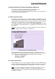
6.7. View Video – ActiveX Mode To view video images from the browser, click View Image – ActiveX Mode from the Welcome screen to access the video images from Internet Explorer as illustrated below: NOTE: When you use Windows XP with Service Pack 2 installed, you will get the message as above! Click on the information text ‘Click here to instal…” and click “Install ActiveX Control…”.
- Camera Name: The Camera name will be displayed when the Camera Name field is entered in the Web Configuration setting under Configuration. In the View Video – ActiveX Mode , you are allowed to use the Upload Video and E-mail Video options. Simply click the desired selection ON or OFF to utilize the options for each of the functions. 6.8.
In the View Video – Java Mode , you are allowed to use the Upload Video and Email Video options. Simply click the desired selection ON or OFF to utilize the options for each of the functions. NOTE: 1. Please refer to the appendix on how to install ActiveX, including 1.) install to the Web Server, and 2.) install to your Local PC. 2. The administrator has the authority to set the upload video function through the setting in the Upload option under Configuration. 3.
7. Using the (Wireless) IP Camera through the IPView SE Utility This chapter describes the IPView SE, which is a powerful software application designed with a user-friendly interface for ease of control and navigation requirements. 7.1. Installation Insert the CD-ROM into the CD-ROM and run the file “IPViewSE Setup.exe” from the directory D:\Install IPView SE\ (Where D:\ is your CD-Rom Drive). Follow the steps onscreen to install the software on your harddisk.
7.2.1. IPView SE control panel Exit Minimize About Add Camera Scan System Config Combine Play Explanation of the Controls in the IPViewSE Control Panel. - System Config - Add Camera - Minimize - Exit - Play - Scan - Combine - About Configure the IPViewSE Control Panel To add a camera to IPView SE Control Panel To minimize the control panel. To close IPView SE. To play back the recorded file. To display for each camera one by one. To combine all display windows in one.
You can select the Input IP button, an Input IP dialog box will appear as illustrated below: Enter the IP Address of the camera in the specified field and click the Add button to add a new camera. Note: 1. If you want to add a camera through the Internet, you must key in a physical IP Address. 2. When the camera is installed behind Gateway and the Open Second Port of camera/Port Forwarding of Gateway function is enabled, the Gateway IP address has to be entered with the Port Number as below: 3.
Make sure to save any changes you have made to keep the information updated. Note : You are allowed to add only one camera at a time. When the user adds the camera, extra icons will appear, including: “Assign IP to Camera”, “Connect/Disconnect”, “Erase”, “Extra Information”. 7.2.3.
7.2.4. The Camera Preview Window When a Camera is selected, a preview window will come up. You can also toggle this window with the “Connect / Disconnect” button in IPView SE. The Camera Window like below will be shown: Wakeup C.P. Minimize Color Setting Maximize View List Close Snapshot Rotate Image Always On Top Zoom Image Click to minimize the display screen of the camera. Click to maximize the display screen of the camera. Click to close the display screen of the camera.
1. Single HDD Reserve Space This option permits reserved HDD space from 500 MB to 1000 MB. 2. Split Recording File From this option, you can adjust the file size for recording the video images (the default setting is 10MB). If the recorded video files reach the file size, video images will be recorded into another file automatically. By File Size - permits recording by file size from 10 MB to 50 MB. - Storage List: This option is used to define the path to save image files.
- Update Firmware firmware options to work with motion detection function. Besides the Alarm Beep, Send Email can be enabled when motion detected. The user can define the time interval to Send E-mail. Enter the File Path and click the Update button, the will be updated automatically.
7.2.8. Email Settings The button “eMail Setting” can be used to send you an email notification when the Camera detects motion. You can enter the needed settings in the screen below: - Mail Server: - Mail From: - Mail To: - Subject: - User Name: - Password: - Interval Time: Mail Server IP or name from your Provider. E-Mail Address of sender. E-Mail Address of receiver. Can be any information to high light the message. Enter the user name in this field.
8. Adding your (Wireless) Internet Camera to your website The (Wireless) Internet Camera can be added to your website, so that every visitor can see what the IP Camera is seeing. To make this work, you need to follow the next steps: 8.1. Xplug Control Installation To Webserver 1. 2. Installation: Copy the “xplug.ocx” file from the directory “ActiveX” on the CD-ROM to any WEB Server table.
The package which is needed to work with the (Wireless) Internet Camera is called “J2SE JRE”. 8.4.2. Add the Code to your Website The following code needs to be added to the website which will show the (Wireless) Internet Camera:
A: The (Wireless) Internet Camera can be connected to LAN with private IP addresses. Q: Can the (Wireless) Internet Camera be installed and work if a firewall exists on the network? If a firewall exists on the network, port 80 is open for ordinary data communication. However, since the Wireless Internet Camera transmits image data, the default port 8481 is also required. Therefore, it is necessary to open port 8481 of the network for remote users to access the (Wireless) Internet Camera. A: 9.2.
A3: a different subnet than your workstation, you will not be able to set the IP address from this workstation. To verify make sure the first 3 sections of the IP address of the (Wireless) Internet Camera corresponds to the first 3 sections of the workstation. Therefore the IP address of the (Wireless) Internet Camera must be set from a workstation on the same subnet. Other possible problems might be due to the network cable. Try replacing your network cable.
configure your display to show at least 65’000 colors for example at least 16bit. NOTE: Applying only 16 or 256 colors on your computer will produce dithering artifacts in the image. A2: The configuration on the (Wireless) Internet Camera image display is incorrect. Through the Web Configuration Image section you need to adjust the image related parameter for improve images such as brightness, contrast, hue and light frequency. Please refer to the Web Configuration section for detail information.
Direct exposure to sunlight ma y cause permanent damage to the CMOS sensor. Therefore do not expose the Internet Camera’s lens directly to sunlight. When operation is required in glaring light environment, it is recommended to use an iris lens. The Internet Camera is designed for indoor usage and if your application requires prolong exposure to sunlight, a sun visor is recommended to protect the Internet Camera. 9.6. Specification 9.6.1.
9.7 Glossary of Terms NUMBERS 10BASE-T 10BASE-T is Ethernet over UTP Category III,IV, or V unshielded twisted-pair media. 100BASE-TX The two-pair twisted-media implementation of 100BASE-T is called 100BASE-TX. 802.11g An IEEE standard for wireless local area networks. It offers transmissions speeds at up to 54 Mbps in the 2.4-GHz band. A Access point It is the hardware interface between a wireless LAN and a wired LAN. The access point attaches to the wired LAN through an Ethernet connection.
the task for network administrators because the software keeps track of IP addresses ra ther than requiring an administrator to manage the task. This means a new computer can be added to a network without the hassle of manually assigning it a unique IP address.
hexadecimal digits. It is easier for humans to read hexadecimal numbers than binary numbers. I IEEE Institute of Electrical and Electronic Engineers. Intranet This is a private network, inside an organization or company, that uses the same software you will find on the public Internet. The only difference is that an Intranet is used for internal usage only. Internet The Internet is a globally linked system of computers that are logically connected based on the Internet Protocol (IP).
NAT Network Address Translator generally applied by a router, that makes many different IP addresses on an internal network appear to the Internet as a single address. For routing messages properly within your network, each device requires a unique IP address. But the addresses may not be valid outside your network. NAT solves the problem. When devices within your network request information from the Internet, the requests are forwarded to the Internet under the router's IP address.
R RARP Reverse Address Resolution Protocol, a TCP/IP protocol that allows a phys ical address, such as an Ethernet address, to be translated into an IP address. RJ-45 RJ-45 connector is used for Ethernet cable connections. Router A router is the network software or hardware entity charged with routing packets between networks. S Server It is a simple computer that provides resources, such as files or other information. SMTP The Simple Mail Transfer Protocol is used for Internet mail.
UTP Unshielded twisted-pair. UTP is a form of cable used by all access methods. It consists of several pairs of wires enclosed in an unshielded sheath. W WAN Wide-Area Network. A wide-area network consists of groups of interconnected computers that are separated by a wide distance and communicate with each other via common carrier telecommunication techniques. Windows Windows is a graphical user interface for workstations that use DOS.