
Instructions / Assembly


10
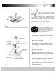
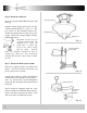
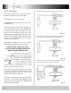
Fig. 17
Fig. 18
Fig. 19
Fan controlled with wall switch and Light controlled at fan.
Fan controlled at fan with Light controlled at wall switch.
Fan & Light controlled by wall switch or switches.
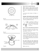
Check that all safety pins, set screws and con-
nections are properly in place and tight.
Check blade clearance and rotation.
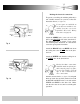
Attach the decorative pull chain tassel(s) to the
switch housing.
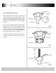
Located on the side of the switch housing is a
slide switch. This switch controls the direction
of blade rotation. The UP position sets the
blades in reverse rotation (air moves UP). The
DOWN position sets the blades in forward rota-
tion (air moves DOWN). Make sure this switch
is all the way UP or DOWN, your fan will not
run if it is in the middle.
Step 8 Final Checks
Illustrations in figures 17, 18 and 19 show
optional wiring diagrams that you can use.
ONLY USE AN OPTIONAL WALL
SWITCH THAT HAS BEEN DESIGNED
FOR USE WITH CEILING FAN
Your dealer carries a number of
different types of wall switches
that have been designed and
tested for use with our products.
To obtain the best performance
electrical components should
be matched for output, for that
reason, we only recommend the use of wall
switch(s) that your dealer provides.
If you elect to control the motor of your ceiling
fan from a wall switch, remember that the wall
switch will only turn your fan on and off. The
speeds can be adjusted at the fan.
If you elect to control the speeds of your ceiling
fan from a wall switch, YOU MUST set the
speed switch on the ceiling fan to HIGH speed
and leave it in that setting.