
Instructions / Assembly


9
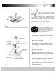
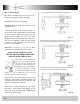
Fig. 14
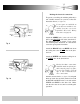
Fig. 15
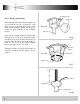
4 or 5 Blade Pattern
Switch Housing
Connector
Motor Housing
Connector
Reverse Switch
Three Speed
Switch
(pull chain)
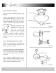
Fig. 16
Remove the large screws in the face of the
motor. Discard any rubber blocks attached to
these screws. The rubber blocks are installed at
the factory to stabilize the motor during ship-
ment.
You have the choice of using 4 or 5 blades (see
figure 14).
Select the correct mounting pattern and attach
each blade to the motor face using pre-installed
screws (see figure 13). Take care not to bend the
blade arms during installation. This will cause
your fan to wobble while running.
Step 6 Blade Assembly Installation
Try mounting the blades on
opposing sides of the motor
face. This will help keep the
fan more level during blade
installation.
Back off (loosen)the three screws on the electri-
cal housing mounting plate attached to the
motor shaft (see figure 16).
A color coded wire connector (female) is locat-
ed inside the electrical switch housing (see fig-
ure 15), a male connector extends from the
mounting plate. Align the colors on each con-
nector and push them together. The connectors
are also notched and will connect only when the
colors are aligned.
The switch housing has three slotted holes
around the top. Align these holes with the three
screws on the mounting plate. Push the switch
housing up and rotate to the right so the screws
are at the far left of the horizontal slot.
Tighten each screw.
Step 7 Electrical Switch Housing Installation