® A Family of Products Owners Manual and Installation Instructions for use with Model Numbers: 52DCO • 52DY • 52DYD 52HS • 52MA Part Number: PL-3020 (Revised 03.10.
READ AND SAVE THESE INSTRUCTIONS Before beginning installation of your new Concord® ceiling fan, read and follow these safety precautions. If you are not familiar with national and local electrical codes and basic electrical wiring procedures, we recommend that you have a qualified electrician install your new ceiling fan. Before you begin, TURN OFF THE ELECTRICITY. Determine which circuit your new fan will be using and remove the fuse or turn off the circuit breaker at the main electrical panel.
This ceiling fan was not designed for installation in any location where it might be exposed to moisture or high humidity. Installation in this type of location could be UNSAFE, will most likely damage the fan and its finish... and will VOID YOUR WARRANTY. Every effort has been made to provide you with proper instructions for the safe installation of this ceiling fan. You could however, encounter situations or problems not covered in this manual.
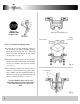
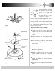
Have you TURNED OFF the Electricity? Ceiling Canopy Mounting Screw Fig. 1 Junction Box Step 1 Attach the mounting bracket Loosen the two canopy mounting screws on the downside face of the mounting bracket. Back them out about half way. This will allow for easier installation of the ceiling canopy later (see figure 1). Install the mounting bracket on the electrical junction box in the ceiling using two machine screws, two washers and two lock washers (see figure 2).
Pull the electric wires in the junction box down through the mounting bracket and then bend them up and back out of the way. This will leave the mounting bracket open and ready to receive the ceiling fan (see figure 4). If you are using an extended support rod, (longer than the one supplied with your fan) remove the half ball from the small support rod that came with the fan and put it on the extended support rod. Make sure to retighten the set screw and insert the safety screw. Fig.
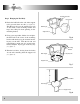
Mounting Bracket Step 3 Hanging the Fan Body Notice the half ball on the end of the support rod is grooved down one side (see figure 6). This Keyway fits over the small keyway pin on the inside of the mounting bracket and keeps the ceiling fan from spinning on the mounting bracket. Keyway Pin Ball Hanger Support Rod Using your step ladder, lift the fan and place the half ball in the center of the mounting bracket with the keyway pin inserted into the keyway on the ball.
Step 4 Making the Electrical Connections To operate your ceiling fan with the pull chain(s) and switches mounted on your fan, follow the instructions below: Green Black Blue If you require or would like to use a different method of controlling your fan, refer to the OPTIONAL ELECTRICAL WIRING PROCEDURES on page 11. White Attach the GREEN wire (connected to the half ball) to the GROUND wire in the junction box. The GROUND wire is usually a bare copper wire without plastic insulation.
Step 5 Attaching the Ceiling Canopy, Canopy Gasket Installation. Slide the ceiling canopy up into place over the ceiling mounting bracket. The two screws on the mounting bracket face should slip through the key hole slots in the canopy (see figure 11). Canopy Rotate the canopy slightly until the screw heads are in the small end of the key hole. Tighten both screws.
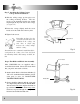
Step 7 Fan Blade Assembly Installation Remove the large screws in the face of the motor. Discard any rubber blocks attached to these screws. The rubber blocks are installed at the factory to stabilize the motor during shipment. (A) 4 Blade Pattern (B) 5 Blade Pattern (C) 4 or 5 Blade Pattern With some CONCORD fans, you have the choice of using 4 or 5 blades (see figure 13C) or you may have purchased a fan with ONLY 4 blades (see figure 13-A) or 5 blades (see figure 13-B).
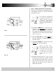
Step 8 Electrical Switch Housing Installation Back off (loosen) the three screws on the electrical housing mounting plate attached to the motor shaft (see figure 16). A color coded wire connector (female) is located inside the electrical switch housing (see figure 15), a male connector extends from the mounting plate. Align the colors on each connector and push them together. The connectors are also notched and will connect only when the colors are aligned.
Fan controlled with wall switch and Light controlled at fan Optional Wiring Diagrams Figure 17 illustrates the wiring used to control the fan with a wall switch plus an optional light fixture controlled at the fixture. Figure 18 illustrates the wiring used to control fan with the pull chain on the electrical switch housing plus an optional light fixture with a wall switch. Fig. 17 Fan controlled at fan with Light controlled at wall switch Fig.
Junction Box Your new CONCORD ceiling fan is now ready for use. Reset your circuit breaker and restore power to the circuit. See the Operation Instructions below to review the function of each control on your fan. Washer and Lock Washer Mounting Bracket Mounting Screw Operation Instructions The pull chain located on the switch housing (see figure 16) controls the speed of your fan.