
Instructions / Assembly


10
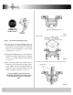
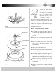
Back off (loosen) the three screws on the
electrical housing mounting plate attached to
the motor shaft (see figure 16).
A color coded wire connector (female) is
located inside the electrical switch housing
(see figure 15), a male connector extends
from the mounting plate. Align the colors on
each connector and push them together.
The connectors are also notched and will
connect only when the colors are aligned.
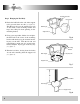
The switch housing has three slotted holes
around the top. Align these holes with the
three screws on the mounting plate. Push the
switch housing up and rotate the the right so
the screws are at the far left of the horizontal
slot.
Tighten each screw.
Step 8 Electrical Switch Housing Installation
Fig. 15
Motor
Housing
Connector
Fig. 16
Reverse
Switch
Switch
Housing
Connector
Electrical
Switch
Housing
Three
Speed
Switch
(pull chain)
Slotted
Mounting
Hole
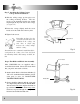
Check all safety pins, set screws and connec-
tions are properly in place and tight.
Check blade clearance and rotation.
Attach the decorative pull chain tassel(s) to
the switch housing.
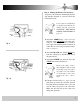
Located on the side of the switch housing is a
slide switch. This switch controls the direc-
tion of blade rotation. The UP position sets
the blades in reverse rotation (air moves UP).
The DOWN position sets the blades in for-
ward rotation (air moves DOWN). Make
sure this switch is all the way
UP or Down,
your fan will not run it it is in the middle.
Step 9 Final Checks