
Instructions / Assembly


11
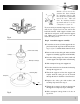
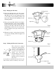
Figure 15 illustrates the wiring used to control
the fan with a wall switch plus an optional light
fixture controlled at the fixture.
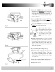
Figure 16 illustrates the wiring used to control
fan with the pull chain on the electrical switch
housing plus an optional light fixture with a wall
switch.
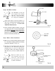
Figure 17 illustrates the wiring used to control
the fan and optional light fixture with separate
wall switches.
Your Concord Dealer can supply you with these
types of switches. It is recommended that you
purchase a Concord brand wall switch. Our
switches have been designed to match the speci-
fications of our ceiling fans. While other brands
of switches will work they may cause unneces-
sary and distracting motor noise.
Optional Wiring Diagrams
IMPORTANT NOTE:
Some wall switches can con-
trol the speeds of a fan motor.
If you decide to use a switch
of this type, YOU MUST
LEAVE THE PULL CHAIN
SWITCH ON THE FAN SET
IN THE HIGH
SPEED
POSITION
AT ALL TIMES.
You can also purchase wall switches that will
adjust the light fixture to different levels of
brightness plus turn it off or on. If you decide to
use a switch of this type, YOU MUST LEAVE
THE LIGHT SWITCH ON THE FAN SET IN
THE ON
POSITION AT ALL TIMES.
Fan controlled at fan with Light controlled at wall switch
Fan controlled with wall switch and Light controlled at fan
Fan & Lights controlled by wall switch or switches
Fig. 15
Fig. 16
Fig. 17