
Specifications


Nexys3 Reference Manual
Doc: 502-182 page 12 of 22
Spartan 6
L12
PIC24FJ192
K_CLK
J13
“HOST”J4
2
L13
K14
K_DAT
M_CLK
M_DAT
R13
R15
DIN
CLK
FPGA Serial
programming
PS/2 Keyboard
PS/2 Mouse
L16
H17
GPIO0
GPIO1
Additional I/O
(for future use)
Spartan-6. Each tile includes two Digital Clock Managers (DCMs) and four Phase-Locked Loops
(PLLs).
DCMs provide the four phases of the input frequency (0º, 90º, 180º, and 270º), a divided clock that
can be the input clock divided by any integer from 2 to 16 or 1.5, 2.5, 3.5... 7.5, and two antiphase
clock outputs that can be multiplied by any integer from 2 to 32 and simultaneously divided by any
integer from 1 to 32.
PLLs use VCOs that can be programmed to generate frequencies in the 400MHz to 1080MHz range
by setting three sets of programmable dividers during FPAG configuration. VCO outputs have eight
equally-spaced outputs (0º, 45º, 90º, 135º, 180º, 225º, 270º, and 315º) that can be divided by any
integer between 1 and 128.
Please refer to the Spartan-6 data sheet at www.xilinx.com for further information on the clock
management tiles.
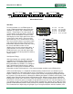
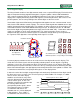
USB-UART Bridge (Serial Port)
The Nexys3 includes an FTDI FT232 USB-UART bridge to allow PC applications to communicate with
the board using standard Windows COM port commands. Free USB-COM port drivers, available from
www.ftdichip.com under the "Virtual Com Port" or VCP heading, convert USB packets to UART/serial
port data. Serial port data is exchanged with the
FPGA using a two-wire serial port (TXD/RXD) and
software flow control (XON/XOFF). After the drivers
are installed, I/O commands from the PC directed to
the COM port will produce serial data traffic on the
N17 and N18 FPGA pins.
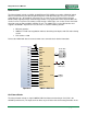
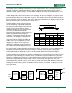
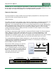
USB HID Host
A Microchip PIC24FJ192
microcontroller provides the Nexys3
with USB H ID host capability.
Firmware in the microcontroller can
drive a mouse or a keyboard attached
to the type A USB connector at J4
labeled "Host". Hub support is not
currently available, so only a single
mouse or a single keyboard can be
used. The PIC24 drives four signals
into the FPGA – two are used as a
keyboard port following the keyboard
PS/2 protocol, and two are used as a
mouse port following the mouse PS/2
protocol.
Two PIC24 I/O pins are also connected to the FPGA’s two-wire serial programming port, so the FPGA
can be programmed from a file stored on a USB memory stick. To program the FPGA, attach a
memory stick containing a single .bit programming file in the root directory, load both M0 and M1 on
J8 jumper, and cycle board power. This will cause the PIC processor to program the FPGA, and any
N17
TXD
N18
Micro-USB
J13
“UART”
2
RXD
Spartan 6
FT232