
Specifications

Nexys3 Reference Manual
Doc: 502-182 page 21 of 22
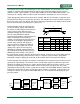
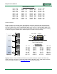
Spartan 6
8
PmodA
8
8
8
PmodB
PmodC
PmodD
Bank2
Bank3
Bank3
Bank0*
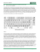
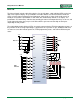
VHDC Connector Pinout
IO1-P:
B2
IO1-N:
A2
IO11-P:
C10
IO11-N:
A10
IO2-P:
D6
IO2-N:
C6
IO12-P:
G9
IO12-N:
F9
IO3-P:
B3
IO3-N:
A3
IO13-P:
B11
IO13-N:
A11
IO4-P:
B4
IO4-N:
A4
IO14-P:
B12
IO14-N:
A12
IO5-P:
C5
IO5-N:
A5
IO15-P:
C13
IO15-N:
A13
IO6-P:
B6
IO6-N:
A6
IO16-P:
B14
IO16-N:
A14
IO7-P:
C7
IO7-N:
A7
IO17-P:
F13
IO17-N:
E13
IO8-P:
D8
IO8-N:
C8
IO18-P:
C15
IO18-N:
A15
IO9-P:
B9
IO9-N:
A9
IO19-P:
D14
IO19-N:
C14
IO10-P:
D11
IO10-N:
C11
IO20-P:
B16
IO20-N:
A16
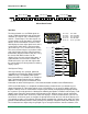
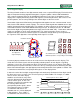
Pmod Connectors
Pmod connectors are 2x6 right-angle, 100-mil female connectors that mate with standard 2x6 pin
headers available from a variety of catalog distributors. Each 12-pin Pmod connector provides two
3.3V VCC signals (pins 6 and 12), two Ground signals (pins 5 and 11), and eight logic signals. VCC
and Ground pins can deliver up to 1A of current. Pmod data signals are not matched pairs, and they
are routed using best-available tracks without impedance control or delay matching.
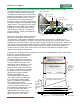
Digilent produces a large collection of Pmod accessory boards that can attach to the Pmod and
VHDC expansion connectors to add ready-made functions like A/D’s, D/A’s, motor drivers, sensors,
cameras and other functions. See www.digilentinc.com for more information.
Pin 1
Pin 12
Pin 6
8 signalsVCC GND
Pmod Connectors – front
view as loaded on PCB
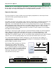
Pmod Pinouts
JA1:
T12
JB1:
K2
JC1:
H3
JD1:
G11
JA2:
V12
JB2:
K1
JC2:
L7
JD2:
F10
JA3:
N10
JB3:
L4
JC3:
K6
JD3:
F11
JA4:
P11
JB4:
L3
JC4:
G3
JD4:
E11
JA7:
M10
JB7:
J3
JC7:
G1
JD7:
D12
JA8:
N9
JB8:
J1
JC8:
J7
JD8:
C12
JA9:
U11
JB9:
K3
JC9:
J6
JD9:
F12
JA10:
V11
JB10:
K5
JC10:
F2
JD10:
E12