
User's Manual Network Adapter JB0, JB1, JB2, JB3


Chapter 4: Appendices – Connectors/Pinouts 4-5
Titan/cPCI User’s Manual, ver. 0.00
Appendix B: Connectors/Pinouts
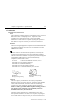
Appendix B outlines the connector pinouts for the Titan/cPCI-2
and the Titan/cPCI-4.
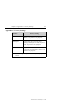
Connector Pinouts
Tables 1 and 2 outline the pinouts for the Titan/cPCI connectors
or cable connectors.
Technical Tip:
Please ensure that you terminate signals if your application does
not use them. Failure to do so may result in a loss of a
performance on your Titan/cPCI adapter.
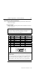
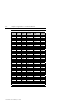
Table 1: DB-9 cable connector pinouts
Pin
No.
RS-232
Signal
Direction
RS-485/422
Signal
Direction
1 DCD input RxD (+) input
2 RxD input RxD (-) input
3 TxD output TxD (+) output
4 DTR output TxD (-) output
5 SG signal ground SR signal reference
6 DSR input CTS (-) input
7 RTS output RTS (+) output
8 CTS input CTS (+) input
9 RI input RTS (-) output
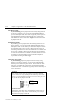
Male DB-9 Connector
1
5
6
9
Cable Part Number:
CAB04DX
Technical Tip:
1. Please ensure that you terminate the DCD or CTS signals if
your application does not use them. The common way to do
this is to connect DCD to DTR and/or to connect CTS to
RTS. Failure to do so may result in a loss of performance